

Pipeline inner wall rust removal robot
A robot and pipeline technology, applied in chemical instruments and methods, machine tools designed for grinding workpiece rotating surfaces, manufacturing tools, etc., can solve the problems of conveying medium pollution, easy rusting of inner walls, etc., to reduce volume and simplify equipment. , the effect of reducing costs
- Summary
- Abstract
- Description
- Claims
- Application Information
AI Technical Summary
Problems solved by technology
Method used
Image

Examples
Embodiment 1
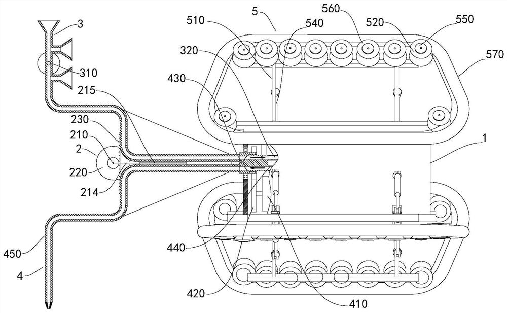
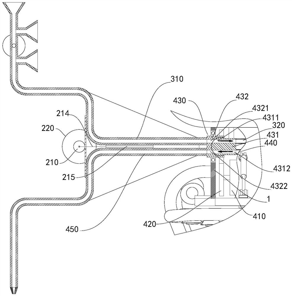
[0035] Such as figure 1 , figure 2 , image 3 As shown, a pipeline inner wall rust removal robot includes a body 1, a rust removal mechanism 2, a dust removal mechanism 3, a painting mechanism 4 and a running mechanism 5, wherein the rust removal mechanism 2, the dust removal mechanism 3, the painting mechanism 4 and the running mechanism 5 They are respectively arranged on the body 1, and the traveling mechanism 5 is used to drive the whole body composed of the body 1, the rust removal mechanism 2, the dust removal mechanism 3 and the paint spraying mechanism 4 to move in the pipeline. The rust removal robot on the inner wall of the pipeline also includes a control module, a control module They are respectively electrically connected to the traveling mechanism 5, the rust removing mechanism 2, the dust removing mechanism 3 and the painting mechanism 4, that is, the control module can respectively control the running mechanism 5, the rust removing mechanism 2, the dust remov...
Embodiment 2
[0037] Such as figure 1 , figure 2 , image 3 As shown, the present embodiment is a further improvement carried out on the basis of embodiment 1, which is specifically as follows:
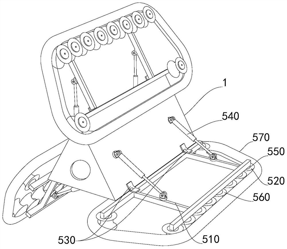
[0038] The number of running gears 5 set on the body 1 is at least three; The body 1 is connected, usually, the hinge assembly 530 can be a hinge; the driving mechanism 550 is arranged on the mounting frame 510; the driving wheel 520 is connected with the driving mechanism 550 and driven to rotate by the driving mechanism 550; the electric push rod a540 One end of the electric push rod a540 is rotatably connected with the body 1, and the other end of the electric push rod a540 is rotatably connected with the middle part of the mounting frame 510 or the end of the mounting frame 510 away from the hinge assembly 530. The angle between them is used to adjust the contact area between the driving wheel 520 and the inner wall of the pipeline; the electric push rod a540 and the driving mechanism 550 a...
Embodiment 3
[0040] Such as figure 1 , figure 2 , image 3 As shown, the present embodiment is a further improvement carried out on the basis of embodiment 2, which is specifically as follows:
[0041] The traveling mechanism 5 also includes a driven wheel 560 and a crawler belt 570. A plurality of driven wheels 560 are rotated at a preset position on the mounting frame 510. The crawler belt 570 goes around the driving wheel 520 and all the driven wheels 560, through the telescopic movement of the electric push rod a540 Change the angle between the installation frame 510 and the body 1 to adjust the contact area between the crawler belt 570 and the inner wall of the pipeline; after the driving mechanism 550 rotates, the driving wheel 520 will be driven to rotate, and the driving wheel 520 will drive all the driven wheels 560 through the crawler belt 570. Rotationally, the drive mechanism 550 is preferably an in-wheel motor.
[0042] The mounting frame 510 includes two beams and at least ...
PUM
 Abstract
Description
Claims
Application Information