
Automatic mold stripping, cooling, marking and charging equipment

A technology of charging equipment and cooling device, which is applied in the field of automatic die-casting, cooling, marking and charging equipment, can solve the problems of slow heat transfer, low cooling efficiency of railway fasteners, and low degree of automation, so as to improve production efficiency and product quality , fast and efficient cooling operation, to achieve the effect of full automation

Active Publication Date: 2020-10-13
HEBEI TIEKE YICHEN NEW MATERIAL TECH CO LTD +1
View PDF11 Cites 1 Cited by
  • Summary
  • Abstract
  • Description
  • Claims
  • Application Information

AI Technical Summary

Problems solved by technology

[0002] Railway fasteners need to be molded, cooled, marked, boiled and other processes after injection molding. At present, they are cooled by water, and the railway fasteners are manually placed in the basket, and the basket is placed in the pool for cooling. When the basket is raised, there are the following problems: 1. The basket is small in size, and the number of railway fasteners installed is small; 2. The railway fasteners are close together, and the heat dissipation is slow; 3. The water in the pool does not flow, and the heat transfer is slow
All the above factors have directly led to low cooling efficiency of railway fasteners, and low degree of automation, wasting manpower and material resources
[0003] At present, when marking, the railway fasteners are manually placed under the laser head of the marking machine to mark one by one, and then taken away. Only one railway fastener can be marked at a time, which is time-consuming and labor-intensive. Low, and after the last cooling process of railway fasteners, there will be water stains on the marking plane, which will affect the marking operation and product quality
[0004] After the marking is completed, the railway fasteners are currently removed from the marking equipment by manipulators, put into the basket, and then manually stacked and then boiled, which is time-consuming and laborious, and the degree of automation is low.

Method used


Image

  • Automatic mold stripping, cooling, marking and charging equipment
  • Automatic mold stripping, cooling, marking and charging equipment
  • Automatic mold stripping, cooling, marking and charging equipment

Examples


Embodiment Construction

[0059] In order to make the purpose, technical solutions and advantages of the present invention clearer, the invention will be clearly and completely described below in conjunction with specific embodiments. It should be understood that the terms "center", "vertical", "horizontal" and "upper" , "Down", "Front", "Back", "Left", "Right", "Vertical", "Horizontal", "Top", "Bottom", "Inner", "Outer", etc. The positional relationship is based on the orientation or positional relationship shown in the drawings, which is only for the convenience of describing the present invention and simplifying the description, rather than indicating or implying that the referred device or element must have a specific orientation, be constructed and operated in a specific orientation, Therefore, it should not be construed as limiting the invention.

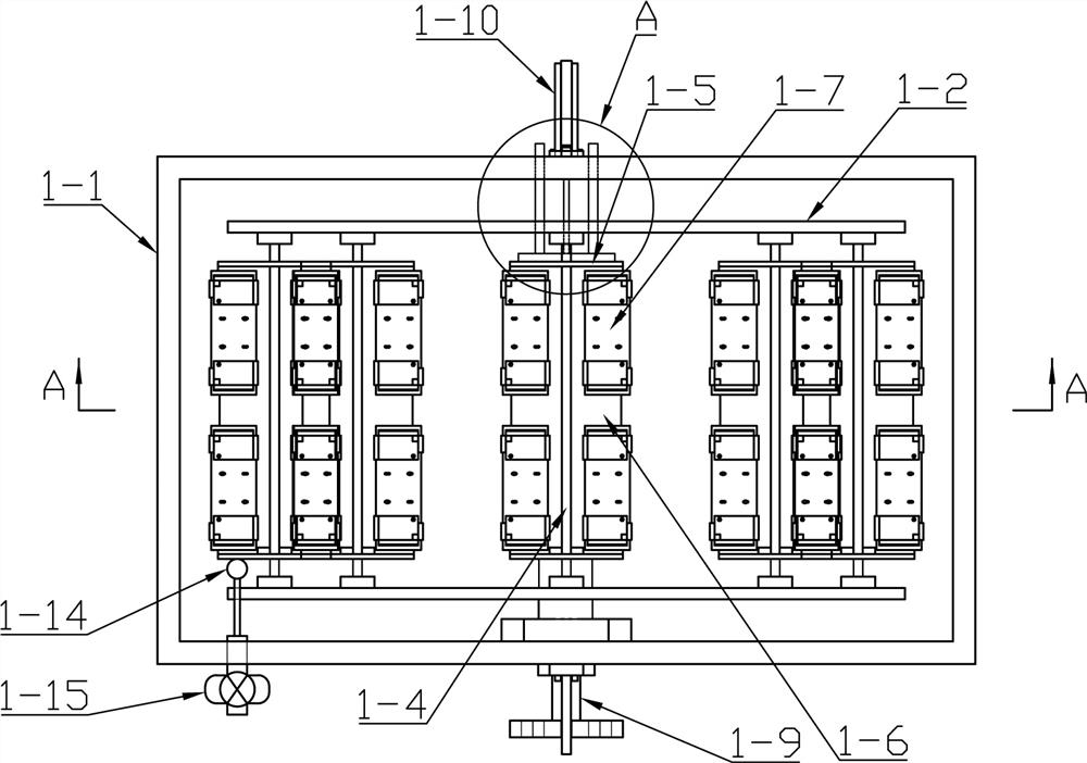
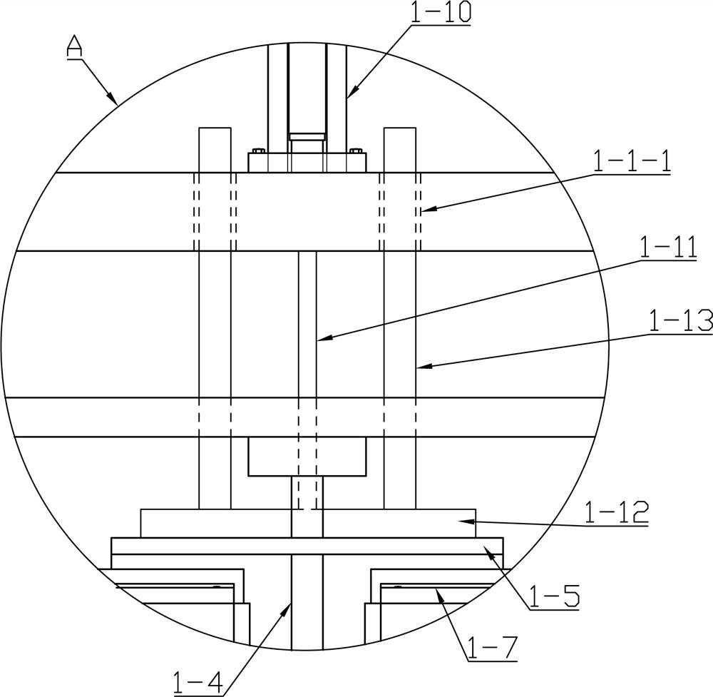
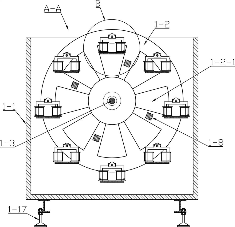
[0060] like Figure 1-Figure 21 Shown is a kind of automatic die cooling marking charging equipment, which includes an injection molding machine, a c...


PUM


Abstract

The invention relates to automatic mold stripping, cooling, marking and charging equipment. The equipment comprises an injection molding machine, a cooling device, a marking machine and a charging device, wherein the marking machine comprises a rack, a first sliding plate and a second sliding plate, wherein the first sliding plate is arranged on the rack and can slide front and back, the second sliding plate is arranged on the first sliding plate and can slide left and right, four sets of positioning mechanisms used for containing railway fasteners are arranged on the second sliding plate in arectangular array mode, and the positioning mechanisms can overturn the railway fasteners; a laser head is arranged above the rack, three sets of water absorption devices are arranged above the rackin the left-right direction, the heights of the water absorption devices correspond to the height of the railway fastener on the positioning mechanism, and the arrangement interval of the water absorption devices is the same as the left-right arrangement interval of the positioning mechanism. The automatic mold stripping, cooling, marking and charging equipment disclosed by the invention is simplein structure and ingenious in design, the injection molding machine, the cooling device, the marking machine and the charging device are matched with a manipulator, full-automatic operation of railway fastener machining is achieved, and the production efficiency and the product quality are greatly improved.

Description

technical field [0001] The invention relates to an automatic die-out cooling, marking and charging equipment, which specifically belongs to the technical field of railway fastener production equipment. Background technique [0002] Railway fasteners need to be molded, cooled, marked, boiled and other processes after injection molding. At present, they are cooled by water, and the railway fasteners are manually placed in the basket, and the basket is placed in the pool for cooling. When the basket is raised, it has the following problems: 1. The basket is small in size and the number of railway fasteners installed is small; 2. The railway fasteners are close together, so the heat is slowly emitted; 3. The water in the pool does not flow, and the heat transfer is slow. All of the above factors have directly led to low cooling efficiency of railway fasteners, and low degree of automation, which wastes manpower and material resources. [0003] At present, when marking, the rail...

Claims


Application Information

Patent Timeline
Patent Type & Authority Applications(China)
IPC IPC(8): B29C45/72B29C45/17B23K26/362B23K26/70
CPCB23K26/362B29C45/17B29C45/1769B29C45/7207B29C2045/1784B23K26/702
Inventor 张远庆仇鹏崔永生高卫峰常杰曹建伟
Owner HEBEI TIEKE YICHEN NEW MATERIAL TECH CO LTD
Learn More