Fatigue-stress relaxation test device for prestressed tendons

A prestressed tendon and stress relaxation technology, which is applied in the field of prestressed tendon material testing, can solve the problems of large time and effort, difficult to consider the performance changes of rebar materials, and high cost, so as to achieve the effect of improving accuracy and guiding design specifications.

Active Publication Date: 2021-04-20
CENT RES INST OF BUILDING & CONSTR CO LTD MCC GRP +1
View PDF5 Cites 0 Cited by
  • Summary
  • Abstract
  • Description
  • Claims
  • Application Information

AI Technical Summary

Problems solved by technology

Tests that only apply prestress without considering service loads only consider a single variable of time, and the test results are inaccurate
The test of axial fatigue tension simulates the service load through axial action, which does not conform to the actual state of service, and the test results are not accurate, and the axial fatigue tensile testing machine is generally expensive, and the price of a single fatigue testing machine is tens of ten thousand yuan
In addition, because the stress relaxation test period of the fatigue testing machine is long (120h ~ 1000h), due to price constraints, it is difficult for the laboratory to test multiple instruments at the same time, and it takes a lot of time and energy to perform fatigue stress relaxation tests under multiple working conditions on a single instrument , and during the waiting process, it is difficult to consider the performance changes of steel bars due to environmental problems, and it is impossible to eliminate the influence of corrosion of steel bars and other materials or other factors on the relaxation performance during storage and waiting

Method used


Image

  • Fatigue-stress relaxation test device for prestressed tendons

Examples


Embodiment Construction

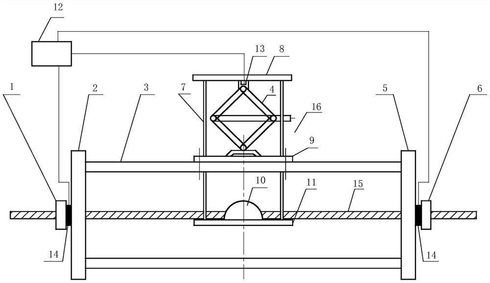
[0019]Such asfigure 1As shown, the fatigue-stress relaxation test apparatus of the prestressed rib of the present invention includes: left anchor 1, left side plate 2, support rod 3, right side plate 5, right anchor 6, load bracket 16, jack 4 However, the data acquisition instrument 12, the force sensor 13, and the stress sensor 14, the left side panel 2 and the right side plate 5 are respectively fixed at both ends of the four support rods 3, and both ends of the four support rods 3 are uniformly fixed to the left. On the periphery of the side panel 2 and the right side plate 5, the reinforcement 15 is passed through the left side plate 2 and the right side plate 5, and the left anchor 1 and the right anchide 6 are fixed to the left side plate after stretching at both ends. 2 and the right side plate 5, between the left anchor 1 and the left side plate 2 and the right anchor 6 and the right side plate 5 are equipped with stress sensor 14, respectively, to be dense 15 is a high stre...


PUM


Abstract

The fatigue-stress relaxation test device of prestressed tendon of the present invention comprises: left anchorage, left side board, support rod, right side board and right anchorage, left side board and right side board are respectively fixed on at least three support rods At both ends, the bars to be tested pass through the left and right plates, and the two ends are respectively fixed on the left and right plates by the left and right anchors, and it also includes: at least one loading bracket and a jack, The loading bracket includes: a tie rod, an upper pull plate, a middle plate, a stopper and a lower plate. One end of at least three tie rods is fixed on the lower plate, and the other ends of the three tie rods pass through the middle plate and are fixed on the upper pull plate. The middle plate is fixed on the On the two supporting rods, the jack is placed on the middle plate, and its upper end withstands the upper pull plate, and the pull-down plate is placed under the rib to be tested. Two blocks are installed on the pull-down plate, and the rib to be tested is stuck between Between the stopper and the pull-down plate, the invention realizes the prestressed tendon relaxation test considering the service load.

Description

Technical field[0001]The present application relates to the field of prestressed material testing technology, in particular, the fatigue-stress relaxation test device for prestressed ribs.Background technique[0002]The prestressed tendon contains the type of prestressed wire, steel strand and steel bars. Due to the long-term high stress, the stress relaxation is developed over time, that is, the total strain remains unchanged in the abutment environment, and the stress over time The phenomenon of gradually decreasing. In the service stage, the phenomenon of the stress relaxation and fatigue load, and there is an accelerated amplification, and the long-term performance of the structure cannot be ignored. The structure is in design, which generally needs to consider the stress loss caused by prestressed relaxation, thereby predicting long-term performance. Does not consider the relaxation acceleration of the service load on the prestressed ribs, which will result in lower estimation, r...

Claims


Application Information

Patent Timeline
IPC IPC(8): G01N3/34G01N3/36G01N3/02
CPCG01N3/02G01N3/34G01N3/36G01N2203/0005G01N2203/0032G01N2203/0048G01N2203/0073G01N2203/0254G01N2203/028G01N2203/0676G01N2203/0682
Inventor 曾滨陈洁陈昕徐曼许庆
Owner CENT RES INST OF BUILDING & CONSTR CO LTD MCC GRP
Why Eureka
Try Eureka