Contactor diagnosis/total voltage acquisition circuit of vehicle power battery

A technology for collecting circuits and vehicle power. It is used in the measurement of current/voltage, only voltage, and instruments. It can solve the problems of high cost and difficult terminal voltage measurement, and achieve reliable diagnosis, reduce measurement difficulty, and improve collection efficiency. Effect

Pending Publication Date: 2020-10-13
郑州宇通集团有限公司 +1
View PDF1 Cites 2 Cited by
  • Summary
  • Abstract
  • Description
  • Claims
  • Application Information

AI Technical Summary

Problems solved by technology

[0005] The purpose of the present invention is to provide a contactor diagnosis / total voltage acquisition circuit of a vehicle power battery, which is used to solve the problem of difficulty and high cost in measuring the terminal voltage of the positive contactor and the negative contactor in the prior art

Method used


Image

  • Contactor diagnosis/total voltage acquisition circuit of vehicle power battery
  • Contactor diagnosis/total voltage acquisition circuit of vehicle power battery

Examples


Embodiment 1

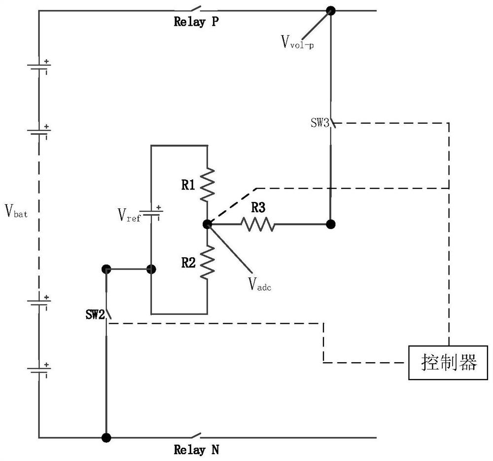
[0019] The design concept of the contactor diagnosis / total voltage acquisition circuit of the vehicle power battery proposed in this embodiment is to diagnose the contactor on the basis of collecting the total voltage of the contactor. This embodiment only collects and diagnoses the total voltage of the positive contactor Relay P, and the specific circuit is as follows figure 1 As shown, when detecting the positive contactor Relay P (that is, the positive control contactor of the high-voltage electrical loop), the contactor diagnosis / total pressure acquisition circuit includes a sampling circuit and a detection branch. The first end of the detection branch is connected to The positive contactor Relay P is away from the end of the power battery (here the end away from the power battery is the end of the positive contactor RelayP connected to other protection devices), and the second end of the detection branch is connected to the negative contactor Relay N (high voltage electric...

Embodiment 2

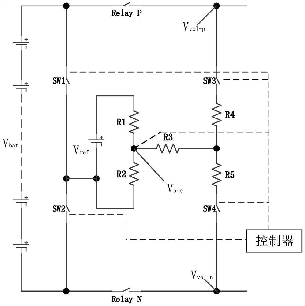
[0039] The design concept of the vehicle power battery contactor diagnosis / total voltage acquisition circuit proposed in this embodiment is the same as the design concept in Embodiment 1, except that in this embodiment, not only the total voltage acquisition and diagnosis can be performed on the positive contactor Relay P, but also It can collect and diagnose the total pressure of the negative contactor Relay N. The circuit can switch the detection of the positive contactor Relay P and the negative contactor Relay N by switching the switch. The specific circuit is as follows figure 2 As shown, the circuit includes the first and second detection branches. The first detection branch is used to detect the positive contactor Relay P. It is basically the same as the circuit structure in Embodiment 1, except that the first detection branch The circuit further includes a fourth voltage dividing resistor R4, and the fourth voltage dividing resistor R4 is connected in series between t...


PUM


Abstract

The invention relates to a contactor diagnosis/total voltage acquisition circuit of a vehicle power battery. The circuit comprises a sampling circuit and a detection branch, a first end of the detection branch is connected to one end, far away from a power battery, of a current to-be-detected contactor, and a second end of the detection branch is connected to one end, close to the power battery, of a non-current to-be-detected contactor; a first switch connected with the first end, a second switch connected with the second end, a plurality of divider resistors and a reference voltage source used for providing forward bias for sampling points of the sampling circuit are arranged in the detection branch; the first switch, the reference voltage source, the first divider resistor, the third divider resistor and the second switch are sequentially connected in series. The reference voltage source and the first divider resistor are connected in series and then connected with the second divider resistor in parallel. A sampling point of the sampling circuit is connected with a series connection point of the first divider resistor and the third divider resistor. The circuit not only realizesthe diagnosis of the contactor, but also can acquire the total voltage of the contactor, thereby greatly reducing the measurement difficulty of the terminal voltage of the contactor.

Description

technical field [0001] The invention relates to a contactor diagnosis / total voltage acquisition circuit of a vehicle power battery, belonging to the high voltage technical field. Background technique [0002] In the application of high-voltage electrical system, in order to control the on-off of the high-voltage electrical system and ensure the safety of the high-voltage loop, it is necessary to introduce a high-voltage contactor to control the on-off of the loop. In the high-voltage embodiment, a high-voltage switch called a high-voltage contactor is placed in the electrical circuit on the high-voltage bus between the battery pack and other protected devices. When the high-voltage electrical system is not in use, the battery pack and other protected devices at the back end The device is automatically disconnected. The high-voltage contactor uses an electromagnet to open and close a conductive mechanical contact connected to the high-voltage bus. The closure of the mechanic...

Claims


Application Information

Patent Timeline
Patent Type & Authority Applications(China)
IPC IPC(8): G01R31/00G01R19/00
CPCG01R19/0084G01R31/00
Inventor 徐童辉张红涛张亚辉龚珍
Owner 郑州宇通集团有限公司
Why Eureka
Try Eureka