
Variable resistor with self-checking and compensation functions

A resistive and variable technology, applied in other resistor networks, resistive elements including multiple resistive elements, etc., can solve problems such as failure to work normally, unreachable working elements, and resistance changes, and achieve simple structure, The effect of preventing short circuit and improving safety

Inactive Publication Date: 2020-10-13
杭州惟昊科技有限公司
View PDF0 Cites 0 Cited by
  • Summary
  • Abstract
  • Description
  • Claims
  • Application Information

AI Technical Summary

Problems solved by technology

In the circuit, resistors generally play the role of protection, voltage division, etc., and when the resistance value of the resistor changes, the voltage distributed on the resistor changes so that the working element cannot meet the requirements of the rated voltage and it cannot work normally; In some special circuits, there may be only one kind of energy-consuming element, the resistor, so when the resistance value changes, the impact on the circuit will be very large, especially when the resistor has been used for a long time and its resistance value becomes At zero time, the circuit will be short-circuited and dangerous
[0003] In some experiments, there are certain requirements for the accuracy of the resistance value of the resistor. If the actual resistance value of the resistor is different from the calibrated resistance value, it will have a considerable impact on the experimental results, and the existing resistors will be damaged after a long time of use. The phenomenon that the resistance value changes occurs, and the present invention makes improvements to the above-mentioned problems

Method used


Image

  • Variable resistor with self-checking and compensation functions
  • Variable resistor with self-checking and compensation functions
  • Variable resistor with self-checking and compensation functions

Examples


Embodiment Construction

[0020] In the description of the present invention, it should be noted that the orientations or positional relationships indicated by the terms "upper", "lower", "inner", "outer", "top / bottom" etc. are based on the orientations shown in the drawings Or positional relationship is only for the convenience of describing the present invention and simplifying the description, but does not indicate or imply that the device or element referred to must have a specific orientation, be constructed and operated in a specific orientation, and therefore should not be construed as limiting the present invention. In addition, the terms "first" and "second" are used for descriptive purposes only, and should not be understood as indicating or implying relative importance.

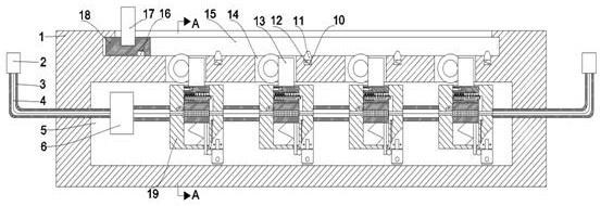
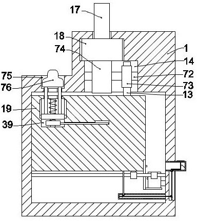
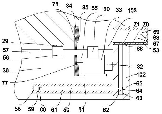
[0021] refer to Figure 1-7, according to an embodiment of the present invention, a variable resistor with self-checking and compensation functions includes a casing 1 and a working chamber 5 provided in the casing 1, and w...


PUM


Abstract

The invention discloses a variable resistor with self-checking and compensation functions. The variable resistor comprises a shell and a working cavity arranged in the shell. Wire conduits and connectors fixedly arranged at the tail ends of the wire conduits are symmetrically arranged at the left and right positions in the left and right walls of the working cavity, and the left and right connectors are communicated through wires arranged in the wire conduits. The variable resistor is simple in structure and convenient to use; with an electromagnet and a transparent tube with the scales, the resistance value of the resistor block can be detected after the resistor block is connected into a loop, and the resistance value of the resistor block can be visually reflected by changing the position of the iron block in the transparent tube. And the iron block can compensate the resistance value of the resistor block through a control device, so that the resistance value of the resistor blockis kept unchanged, and the working current in the circuit cannot be changed. And meanwhile, a safety resistor is arranged, so that the phenomenon of short circuit of the circuit is prevented, and thesafety in use is improved.

Description

technical field [0001] The invention relates to the technical field of electronic components, in particular to a variable resistor with self-checking and compensation functions. Background technique [0002] In daily life or experiments, resistance is an electronic component that is often used. In the circuit, resistors generally play the role of protection and voltage division, and when the resistance value of the resistor changes, the voltage divided by the resistor changes so that the working element cannot meet the requirements of the rated voltage and it cannot work normally; In some special circuits, there may be only one kind of energy-consuming element, the resistor, so when the resistance value of the resistor changes, it will have a great impact on the circuit, especially when the resistor has been used for a long time and its resistance value becomes At zero time, the circuit will be short-circuited and dangerous. [0003] In some experiments, there are certain ...

Claims


Application Information

Patent Timeline
IPC IPC(8): H01C10/16H01C1/16
CPCH01C1/16H01C10/16
Inventor 柏见生
Owner 杭州惟昊科技有限公司
Learn More