
Cable laying device for electric power engineering construction and using method

A technology of electric power engineering and cables, which is applied in the field of cable laying devices, can solve the problems of heavy workload and low work efficiency of staff, and achieve the effects of reducing workload, improving work efficiency, and improving work efficiency

Inactive Publication Date: 2020-10-13
河北荣威电力工程有限公司
View PDF8 Cites 6 Cited by
  • Summary
  • Abstract
  • Description
  • Claims
  • Application Information

AI Technical Summary

Problems solved by technology

[0004] In view of the above-mentioned related technologies, the inventor believes that there are defects that multiple workers are required to pull the cables, and at the same time, the workload of the workers is large and the work efficiency is low.

Method used


Image

  • Cable laying device for electric power engineering construction and using method
  • Cable laying device for electric power engineering construction and using method
  • Cable laying device for electric power engineering construction and using method

Examples


Embodiment Construction

[0039] The following is attached Figure 1-4 The application is described in further detail.

[0040] The embodiment of the present application discloses a cable laying device used in power engineering construction.

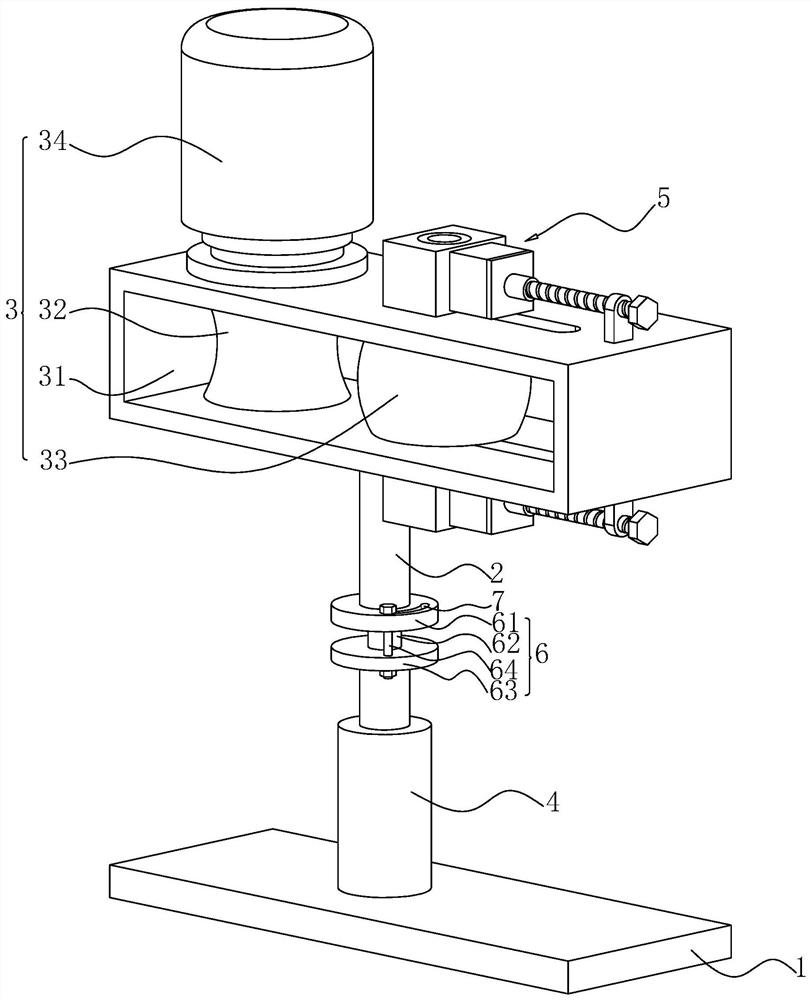
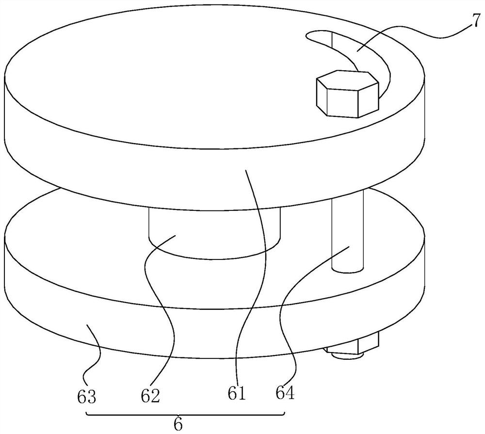
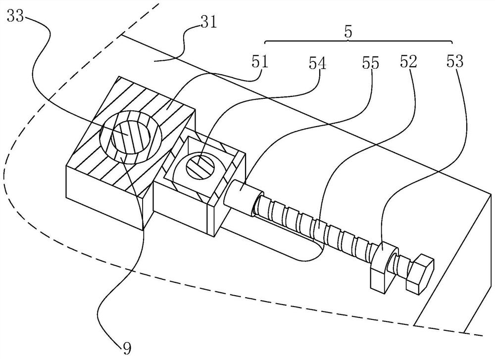
[0041] refer to figure 1, including a base plate 1 and a support column 2, the support column 2 is fixedly connected to the upper surface of the base plate 1, and the end of the support column 2 away from the base plate 1 is provided with a wiring assembly 3 for transmitting cables, and the wiring assembly 3 includes a wiring frame 31 and a driving wheel 32 , the driven wheel 33 and the rotating motor 34, the wiring frame 31 is a rectangular plate structure, the wiring frame 31 is fixedly connected with the support column 2, and the support column 2 is perpendicular to the lower surface of the wiring frame 31, the driving wheel 32 and the driven wheel 33 are all located In the wiring frame 31, the axis of rotation of the driving wheel 32 and the driven wheel 33...


PUM


Abstract

The invention relates to a cable laying device for electric power engineering construction and a using method. The device comprises a bottom plate and a supporting column; the supporting column is fixedly connected to the center of the upper surface of the bottom plate; the end, away from the bottom plate, of the supporting column is fixedly connected with a wiring assembly used for conveying a cable; the wiring assembly comprises a wiring frame, a driving wheel, a driven wheel and a rotating motor; the lower surface of the wiring frame is fixedly connected with the supporting column; the driving wheel and the driven wheel are positioned in the wiring frame; the rotating axis of the driving wheel and the rotating axis of the driven wheel are perpendicular to the lower surface of the wiringframe; a rotating shaft of the driving wheel penetrates through the side wall of the wiring frame and is rotationally connected with the wiring frame; the rotating motor is fixedly connected to the upper surface of the wiring frame; and an output shaft of the rotating motor is fixedly connected with the rotating shaft of the driving wheel; a rotating shaft of the driven wheel penetrates through the wiring frame and is rotatably connected with the wiring frame; and a gap used for containing the cable is formed between the driving wheel and the driven wheel.

Description

technical field [0001] The present application relates to the technical field of cable laying devices, in particular to a cable laying device and a usage method for power engineering construction. Background technique [0002] Cable laying refers to the process of laying and installing cables along the surveyed route to form a cable line. According to the application occasion, it can be divided into several laying methods such as overhead, underground pipeline, underground direct burial, underwater, wall and tunnel. Reasonable selection of cable laying method is very important to ensure the transmission quality, reliability and construction maintenance of the line. [0003] In the existing cable laying process, the cable is wound on the winding roller. When the cable is routed and laid out, due to the heavy weight of the cable, multiple workers are required to pull the cable, so as to realize the cable layout. After the laying is completed, fix the cables to complete the la...

Claims


Application Information

Patent Timeline
IPC IPC(8): H02G1/06B65H51/10
CPCB65H51/10H02G1/06
Inventor 郭保强
Owner 河北荣威电力工程有限公司
Learn More