
Vascular clamp

A technology of vascular clips and clamping parts, applied in the field of vascular clips, which can solve the problems of tissue damage, many surgical operation steps, and large volume occupation, and achieve the effects of reducing pulling and damage, small size, and liberating surgical operation space

Pending Publication Date: 2020-10-16
GUANGDONG UNIV OF TECH
View PDF0 Cites 2 Cited by
  • Summary
  • Abstract
  • Description
  • Claims
  • Application Information

AI Technical Summary

Problems solved by technology

[0007] The purpose of the present invention is to overcome the defects of the above-mentioned existing vascular clips, such as many surgical operation steps, easy pulling and twisting of blood vessels causing tissue damage, and large volume occupying the surgical field of view, to provide a vascular clip whose center of gravity is lower than the blood vessels when in use. Can reduce tissue damage caused by pulling and twisting, and the volume does not occupy the field of view during operation

Method used


Image

  • Vascular clamp
  • Vascular clamp
  • Vascular clamp

Examples


Embodiment Construction

[0030] The technical solutions in the embodiments of the present invention will be clearly and completely described below in conjunction with the accompanying drawings in the embodiments of the present invention. Obviously, the described embodiments are only some, not all, embodiments of the present invention. All other embodiments obtained by ordinary persons in the art without creative efforts belong to the protection scope of the present invention.

[0031] In the description of this application, it is to be understood that the terms "upper", "lower", "front", "rear", "vertical", "horizontal", "top", "bottom", "inner", The orientation or positional relationship indicated by "outside" is based on the orientation or positional relationship shown in the drawings, and is only for the convenience of describing the application and simplifying the description, rather than indicating or implying that the referred device or element must have a specific orientation, constructed and o...


PUM


Abstract

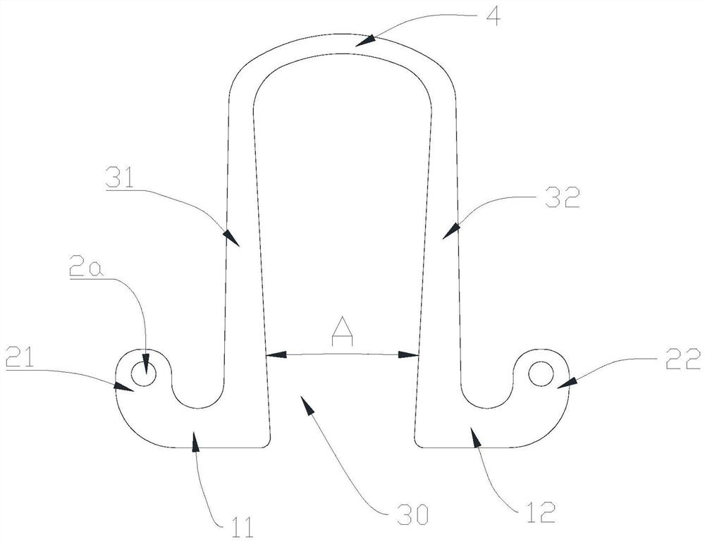
The invention discloses a vascular clamp. The vascular clamp comprises a first supporting portion, a second supporting portion, a first operating portion, a second operating portion, a first clampingportion, a second clamping portion and a deformation portion, wherein the first supporting portion and the second supporting portion are arranged in a separated mode; the first operating portion extends upwards from the first end of the first supporting portion, and the second operating portion extends upwards from the first end of the second supporting portion; the first clamping portion extendsupwards from the second end of the first supporting portion, and the second clamping portion extends upwards from the second end of the second supporting portion; the distance between the first clamping portion and / or the second supporting portion and a middle vertical plane between the first supporting portion and the second supporting portion is gradually increased upwards from the first supporting portion or the second supporting portion; and the deformation portion is connected with an extending end of the first clamping portion and an extending end of the second clamping portion, and thedeformation portion can be deformed by operating the operating portions. When the vascular clamp is used, the gravity center of the vascular clamp is lower than that of a blood vessel, tissue damage caused by pulling and twisting can be reduced, and the vascular clamp is suitable in size and does not occupy the view during operation.

Description

technical field [0001] The invention relates to the technical field of medical instruments, in particular to a blood vessel clip used in clinical operations. Background technique [0002] Vascular clamp refers to a device used to block blood flow and continuously clamp blood vessels during clinical operations. In plastic surgery, neurosurgery and microsurgery, blood vessels are delicate and easily damaged, and the consequences of vascular injury are serious. Existing vascular clamps generally include an upper clamp and a lower clamp, and the upper clamp and the lower clamp are connected by a rotating shaft, so that the upper clamp and the lower clamp at the front end of the rotating shaft form a clamping part, and the upper clamp and the lower clamp at the rear end of the rotating shaft Part of the lower clamp constitutes the handle. There is following problem in existing this vascular clip: [0003] (1) There are many surgical steps. Existing hemostatic clips must cut o...

Claims


Application Information

Patent Timeline
Patent Type & Authority Applications(China)
IPC IPC(8): A61B17/122
CPCA61B17/122A61B2017/12004
Inventor 王成勇刘志华
Owner GUANGDONG UNIV OF TECH
Learn More