Supercharge Your Innovation With Domain-Expert AI Agents!

Two-way grasping forceps for digestive endoscope

A digestive endoscope and grooved plate technology, applied in the field of medical devices, can solve the problems of difficult-to-fix and pull tissue moving relative to each other, large tissue moving distance, tissue damage, etc.

Active Publication Date: 2021-05-14
中国人民解放军陆军第七十三集团军医院 +1
View PDF5 Cites 0 Cited by
  • Summary
  • Abstract
  • Description
  • Claims
  • Application Information

AI Technical Summary

Problems solved by technology

[0005] 2. The force applied by the existing clamping device during clamping is divided into horizontal force and vertical force. The force in the horizontal direction makes the tissue close the perforation, and the force in the vertical direction pulls the tissue upward. Move, when clamping, it needs to apply more force, and pull the tissue to move a larger distance, which is easy to cause tissue damage
[0006] 3. It is difficult for the currently used clips to fix the moving distance of the pulled tissue in real time during the clamping process

Method used


Image

  • Two-way grasping forceps for digestive endoscope
  • Two-way grasping forceps for digestive endoscope
  • Two-way grasping forceps for digestive endoscope

Examples


Embodiment 1

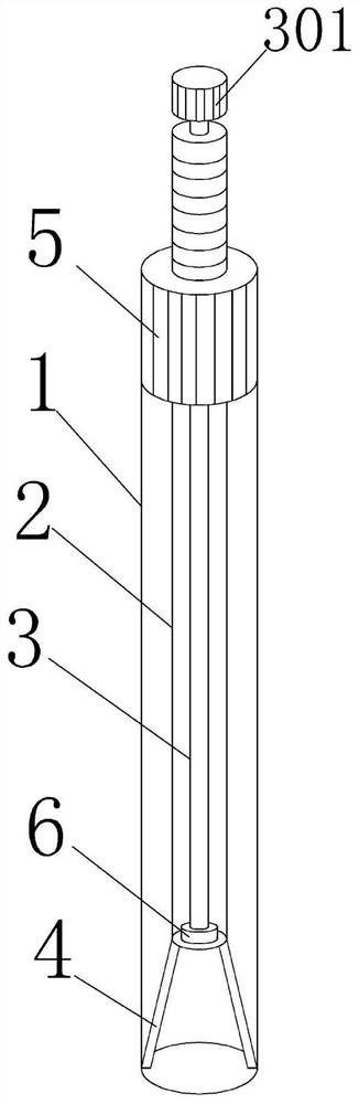
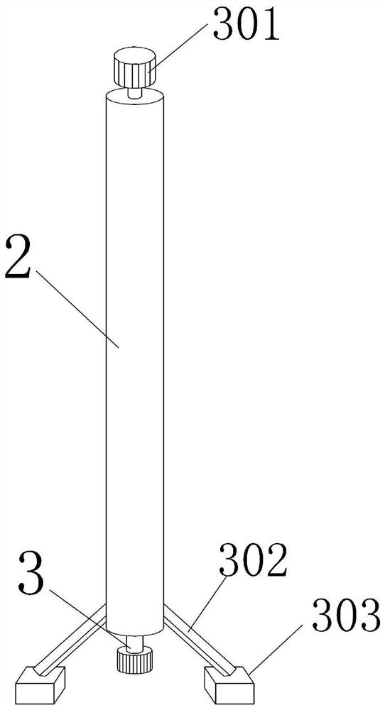
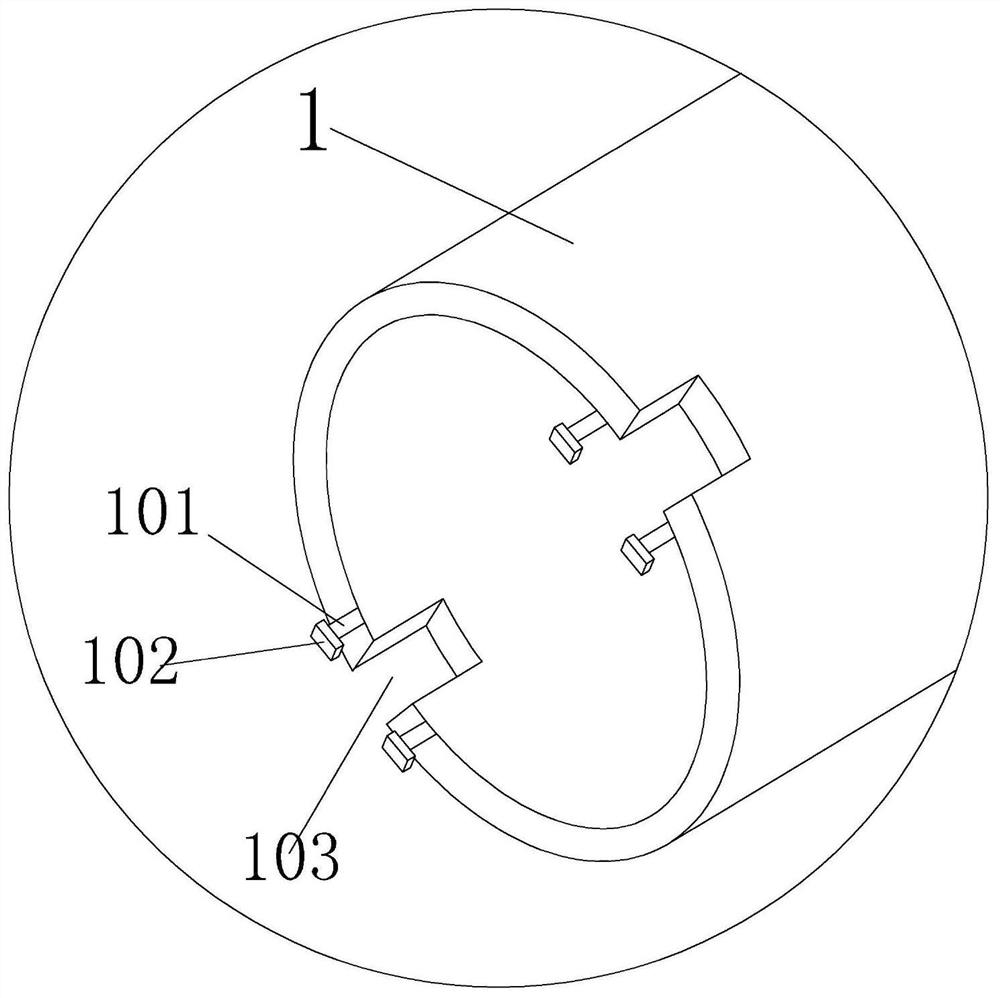
[0032] refer to Figure 1-4 As shown, a two-way grasping forceps for digestive endoscope includes a sleeve 1, a pusher 2, a rotating rod 3, and a closing mechanism 4. One end of the sleeve 1 is rotated with a screw sleeve 5, and the other end is symmetrically provided with grooves. 103, and are symmetrically hinged on both sides of the groove 103 with a foot column 101, and the end of the foot column 101 is hinged with a foot piece 102; the pusher 2 is installed in the casing 1 and the outer wall is threaded with the screw sleeve 5; Rotating rod 3 is installed inside push cylinder 2 and is provided with main gear 6 on the end that is positioned at sleeve pipe 1, and the end that is positioned at outside push cylinder 2 is provided with nut 301; , Push tube 2 is hinged, and with the up and down movement of push tube 2 closing mechanism 4 draws in or unfolds, and the closing mechanism 4 after unfolding moves relatively with rotating rod 3 rotations, and the position when closing...

Embodiment 2

[0035] Based on Embodiment 1, the gear teeth 11 on the tooth plate 703 form an acute angle with the tooth plate 703 and the gear teeth 11 are inclined toward the closed end of the slot plate 7, and the gear teeth 11 on the horizontal plate 9 form an acute angle with the horizontal plate 9 And mesh with the upper gear teeth 11 of the tooth plate 703 . When pulling the tissue on both sides of the perforation position, the real-time position can be kept fixed, and the closing mechanism 4 will not slip due to the tension of the tissue, avoiding repeated pulling and closing.

[0036] One end of the vertical plate 8 exceeds the end of the horizontal plate 9 , and the end of the vertical plate 8 beyond the horizontal plate 9 is located in the chute 701 after the closing device 4 is deployed.

[0037] The fixing mechanism is a plurality of crotch hooks 10 arranged on the bottom ends of the groove plate 7 and the clamping plate, and the bending directions of the crotch plate 7 and the ...

Embodiment 3

[0039]Based on Embodiment 1, the fixing mechanism is a plurality of adsorption holes arranged on the bottom of the slotted plate 7 and the clamping plate, and the inside of the connecting rod 302 and the inside of the push cylinder 2 are provided with an air passage connected to the adsorption holes. The airway is connected to an air pump. Through the two suction holes of the air pump, the tissues on both sides of the perforation site are adsorbed and then closed.


PUM


Abstract

The invention discloses a bidirectional grasping forceps for digestive endoscope, comprising a sleeve, a push cylinder, a rotating rod and a closing mechanism. The two sides of the groove are symmetrically hinged with foot posts, and the end of the foot post is hinged with a foot block; the push cylinder is installed in the casing and the outer wall is threadedly connected with the screw sleeve; the rotating rod is installed inside the push cylinder and is located in the casing. The end is provided with a main gear, and the end located outside the push cylinder is provided with a nut; the closing mechanism is hinged with the foot post and the push cylinder respectively, and the closing mechanism is folded or unfolded with the up and down movement of the push cylinder. The mechanism moves relatively with the rotation of the rotating rod, and the position of the closing mechanism is fixed in real time when the rotating rod moves. When pulling and closing the tissue, use horizontal force to better close the perforation site and reduce tissue damage.

Description

technical field [0001] The invention relates to the technical field of medical instruments, in particular to a bidirectional grasping forceps for digestive endoscope. Background technique [0002] Gastrointestinal perforation is a common surgical acute abdomen in clinical practice. Save the patient from suffering huge surgical trauma; at present, clips are mainly used for clamping and closing. When using clips for clamping and closing, the clip has an angle relative to the tissue, and the contact with the tissue is small and it is easy to pierce the tissue when clamping; and the existing clamping The force exerted by the device during clamping is divided into horizontal force and vertical force. The force in the horizontal direction makes the tissue close the perforation, and the force in the vertical direction pulls the tissue to move upward. Greater force is applied, and the moving distance of the pulled tissue is larger, which is likely to cause tissue damage; and it is ...

Claims


Application Information

Patent Timeline
Patent Type & Authority Patents(China)
IPC IPC(8): A61B17/29
CPCA61B17/29A61B2017/00818A61B2017/2926
Inventor 徐斌沙素梅涂永久刘珊珊
Owner 中国人民解放军陆军第七十三集团军医院
Features
  • R&D
  • Intellectual Property
  • Life Sciences
  • Materials
  • Tech Scout
  • Unparalleled Data Quality
  • Higher Quality Content
  • 60% Fewer Hallucinations
Learn More