Clamping mechanism for roller processing and using method thereof

A clamping mechanism and roller technology, applied in metal processing machinery parts, clamping devices, metal processing and other directions, can solve the problems of inconvenient roll movement, inconvenience in roll rotation, time-consuming and laborious adjustment process, etc., and achieve compact installation and stable use. Effect

Active Publication Date: 2020-10-16
马鞍山欧凯新材料科技有限公司
View PDF14 Cites 1 Cited by
  • Summary
  • Abstract
  • Description
  • Claims
  • Application Information

AI Technical Summary

Problems solved by technology

At present, there is no universal motorized fixture for roll processing in China. In metallurgical equipment manufacturing enterprises, the traditional clamping method is often used to install the roll with a V-shaped seat, and then adjust the roll through the contoured iron or through the spiral top. For the position in the height direction, if it is necessary to adjust the axis line of the roll to be parallel or perpendicular to the feed direction of the machine tool, the adjustment is more difficult, and it is often completed through repeated trial adjustments
In addition, the weight of metallurgical rolls

Method used


Image

  • Clamping mechanism for roller processing and using method thereof
  • Clamping mechanism for roller processing and using method thereof
  • Clamping mechanism for roller processing and using method thereof

Examples


Example Embodiment

[0030] The following will clearly and completely describe the technical solutions in the embodiments of the present invention with reference to the accompanying drawings in the embodiments of the present invention. Obviously, the described embodiments are only some, not all, embodiments of the present invention. Based on the embodiments of the present invention, all other embodiments obtained by persons of ordinary skill in the art without creative efforts fall within the protection scope of the present invention.

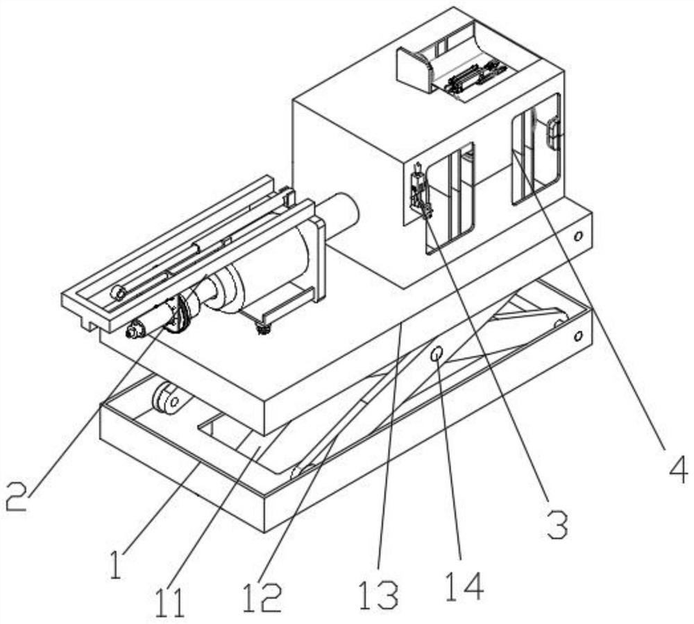
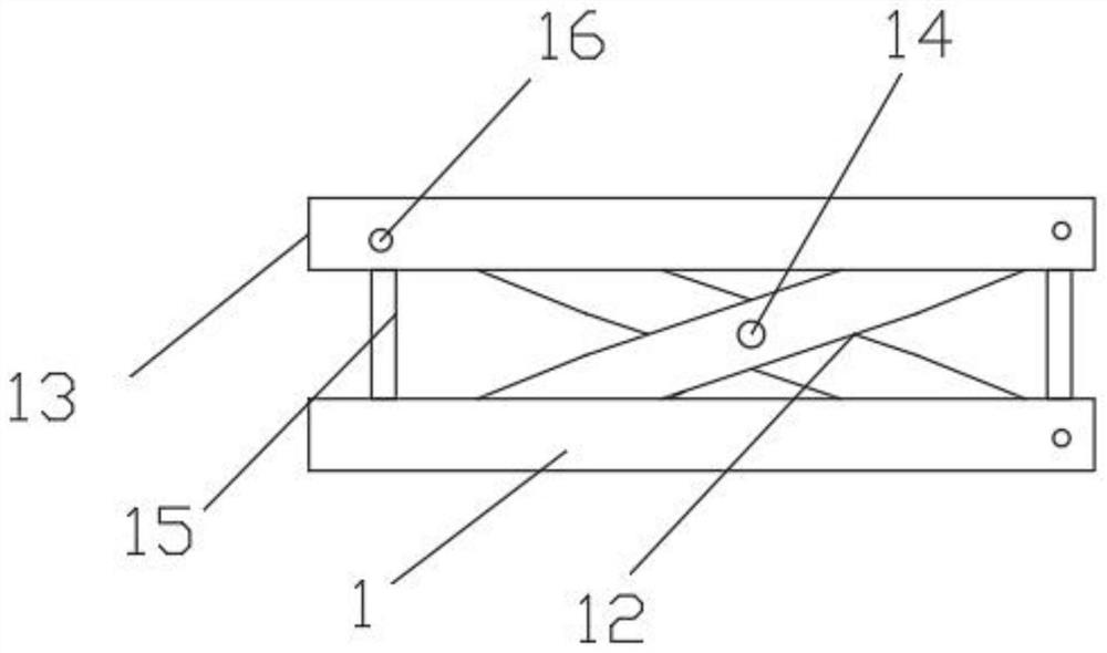
[0031] see Figure 1-7 As shown, a clamping mechanism for roll processing includes a base 1, a pushing mechanism 2, a locking mechanism 3, and a box body 4. The interior of the base 1 is intersected with two elevating arms 12, and the two elevating arms 12 are connected by a rotating shaft 14, one end of the rotating shaft 14 is connected to the cylinder one 11 through a sleeve, the other end of the cylinder one 11 is connected to the inner wall side of the base 1,...


PUM


Abstract

The invention discloses a clamping mechanism for roller processing and a using method thereof. The clamping mechanism is provided with three blocking slots, three bulges, three clamping blocks and three U-shaped slots, wherein the U-shaped slots are adaptive to the bulges, and the blocking slots are adaptive to the clamping blocks, so that the clamping blocks are conveniently mounted, are mountedmore compactly, and are more stable in use. The using method of the clamping mechanism comprises the following steps: inserting a roller into an arc-shaped slot, starting a gas cylinder III, pushing apush rod to move by a piston rod, pushing a push block to move by the push rod, pushing a circular ring to move by the push block, pushing a support rod II and a slide sleeve to move, sliding the slide sleeve in a slide hole I, pushing the front ends of the clamping blocks to extrude the roller, pulling elastic parts to be the longest at the rear ends of the clamping blocks through cushion plates, and clamping the roller through the three clamping blocks. The clamping blocks, springs, the elastic parts and the cushion plates are arranged, so that the clamping mechanism has good buffer property, and is convenient in fixing the roller; and meanwhile, rollers of different diameters are conveniently fixed, so that the range of application is wide.

Description

technical field [0001] The invention relates to the technical field of roll processing, in particular to a clamping mechanism for roll processing and a use method thereof. Background technique [0002] In the roll processing process, a floor boring machine or a special machine tool is often used to complete the center hole punching and finishing center hole processes, and some rolls also need to complete the milling, drilling, nesting and other processes on the boring machine. Position adjusted and clamped. At present, there is no universal motorized fixture for roll processing in China. In metallurgical equipment manufacturing enterprises, the traditional clamping method is often used to install the roll with a V-shaped seat, and then adjust the roll through the contoured iron or through the spiral top. For the position in the height direction, if it is necessary to adjust the axis line of the roll to be parallel or perpendicular to the feed direction of the machine tool, ...

Claims


Application Information

Patent Timeline
IPC IPC(8): B23Q3/00B23Q7/00
CPCB23Q3/00B23Q7/00B23Q2703/10
Inventor 杨传坤
Owner 马鞍山欧凯新材料科技有限公司
Why Eureka
Try Eureka