
Pneumatic numerical control shot blasting machine

A shot blasting machine, pneumatic technology, applied in the direction of abrasive jet machine tools, spray guns, metal processing equipment, etc., can solve the problems of inability to stretch, unable to eliminate the stress of the elbow workpiece, and incomplete shot peening on the inner wall of the elbow, so as to improve the fixation degree of effect

Active Publication Date: 2020-10-16
河南诺信腾达电子科技有限公司
View PDF19 Cites 3 Cited by
  • Summary
  • Abstract
  • Description
  • Claims
  • Application Information

AI Technical Summary

Problems solved by technology

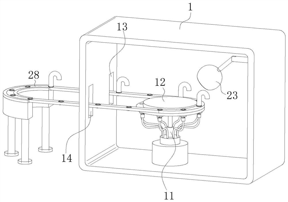
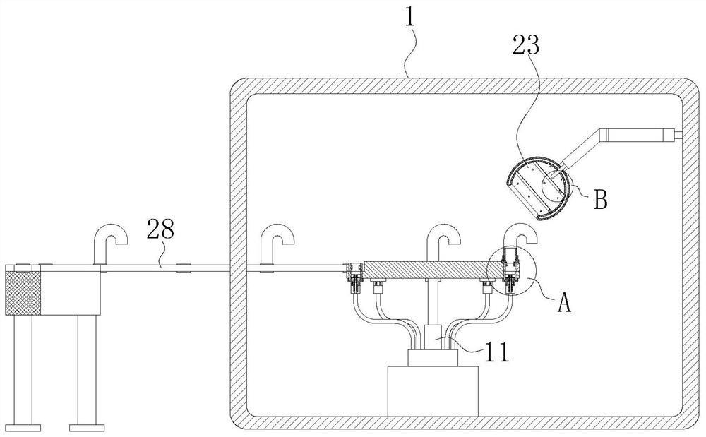
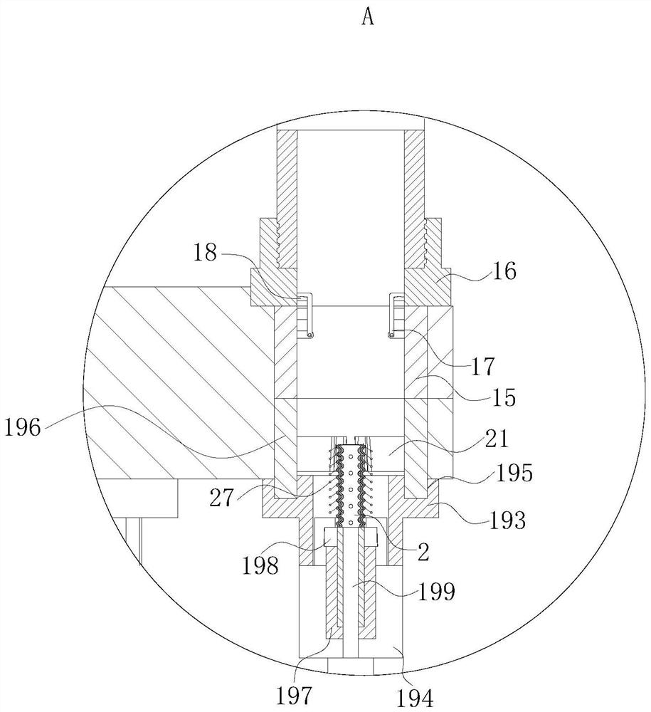
[0008] During work, most of the shot blasting machines in the prior art are blasting plate or block workpieces, but when blasting tubular or elbow shaped workpieces, because the nozzle of the shot blasting machine is on the elbow The inside of the workpiece cannot be stretched, resulting in incomplete shot peening on the inner wall of the elbow, and the problem that the stress in the elbow workpiece cannot be eliminated. The shot blasting machine made by the present invention can extend the stretch layer into the elbow workpiece, and cooperate with the stretching The rotation of the layer can effectively carry out shot blasting to elbow workpieces. When using the shot blasting machine made by the present invention, first start the shot blasting machine, and then place the elbow workpieces vertically on the conveyor belt. It is connected with the first magnetic ring arranged evenly, so that the elbow can be adsorbed on the first magnetic ring. When the motor drives the rotating disk to rotate, the rotating disk can drive the conveyor belt to move into the body through the inlet. When the conveyor belt When the elbow is driven through the entrance, the conveyor belt stops rotating at this time, and at the same time the controller controls the first electric push rod to stretch upwards. When the first electric push rod drives the second electric push rod to move to both sides of the clamp rod, the two-way telescopic The rod starts to shrink, and at the same time the second electric push rod stretches upwards. During this process, the clamping rod can be pushed into the top of the first circular groove and stuck on the clamping block. During this process, the degree of fixing of the elbow can be improved, thereby preventing The elbow is tilted during the shot peening process, causing it to fall off. Since the first circular groove corresponds to the second circular groove, when the conveyor belt moves to the rotating disk with the elbow, the first circular groove and the second circular groove The circular slots correspond one by one, and at the same time the first magnetic ring and the second magnetic ring attract each other. When the first magnetic ring and the second magnetic ring are attracted to each other, the controller controls the motor at the bottom of the support block to rotate, and controls the second magnetic ring to rotate. The second electric telescopic rod stretches, and at the same time, the controller controls the storage box to blow shot peening into the long pipe through the conduit. When the second electric telescopic rod stretches into the first circular groove, the stretched layer extends into the lumen of the elbow, and at the same time The first gear and the gear teeth mesh with each other, and the second magnetic ring can be driven to rotate during the rotation of the motor. Since the second and first magnetic rings are attracted to each other, the elbow can be driven to rotate through the first magnetic ring. When the long tube is sprayed into the stretching layer, the stretching layer is pressed by the gas, which can push the stretching layer to expand upwards and fill in the lumen of the elbow. In this process, the inner wall of the elbow can be shot peened, and the inner wall of the elbow can be evenly sprayed during this process, so that the stress on the inner wall of the elbow can be eliminated, and at the same time, the rotation of the stretching layer driven by the motor can be used. Further improve the degree of spraying on the inner wall of the elbow, so that the stress on the inner wall of the elbow can be completely eliminated. When the rotating disc drives the elbow to move to the position of the mechanical arm, the controller controls the rotating disc to stop rotating and controls the mechanical arm to drive The first nozzle sprays the outer surface of the elbow. In this process, the outer surface of the elbow can be sprayed evenly, so that the stress on the outer surface of the elbow can be eliminated. Spray the outer surface of the elbow, and the stress on the outer surface of the elbow can be further eliminated in the process. After the elbow is sprayed, the conveyor belt drives the elbow to move out of the body. At the mouth, because the capsule is fixedly connected to the outlet, when the elbow touches the capsule, it will rotate. During this process, the elbow will drive the block to rotate, so that the lever can fall off the block. In this process, it will be more convenient collection

Method used


Image

  • Pneumatic numerical control shot blasting machine
  • Pneumatic numerical control shot blasting machine
  • Pneumatic numerical control shot blasting machine

Examples


Embodiment approach

[0033] As an embodiment of the present invention, the side of the first spray head 22 close to the machine body 1 is provided with a spray cover 23 in the inner wall of the manipulator, and the spray cover 23 is designed to rotate; the inner wall of the spray cover 23 is provided with an arc shaped groove 24, and the arc shaped groove 24 communicates with the storage box through a tube; the inner wall of the arc shaped groove 24 is provided with evenly arranged spouts;

[0034] When working, because the first spray head 22 is connected with the spray cover 23 outside the rotation, it can prevent the shot from flying around during the spraying process of the first spray head 22, thereby increasing the collection of the shot shot. Since the inner wall of the spray cover 23 has an arc Groove 24, the gas can blow the shot into the arc groove 24, when the shot flows into the arc groove 24, it can be sprayed out through the evenly arranged nozzles, and the outer surface of the elbow ...


PUM


Abstract

The invention belongs to the technical field of shot blasting machines, and particularly relates to a pneumatic numerical control shot blasting machine. The pneumatic numerical control shot blasting machine comprises a machine body and a conveyor belt, and the inner surface of the machine body is fixedly connected with a storage box on the bottom end surface of the machine body; the upper end faceof a first electric extendable rod is fixedly connected with a rotating disc, and a first annular groove is formed in the inner wall of the rotating disc; a conveying belt is rotationally connected into the first annular groove, and the other end of the conveying belt extends out of the machine body through an inlet and an outlet; and first circular grooves are uniformly formed in the inner wallof the conveying belt, a first magnetic ring is rotationally connected in the inner wall of each circular groove, and an elbow is adsorbed on each first magnetic ring. The shot blasting machine is mainly used for solving the technical problems that in the prior art, most shot blasting machines conduct shot blasting on plate-shaped or block-shaped workpieces, however, when shot blasting is conducted on tubular or elbow-shaped workpieces, due to the fact that spray heads of the shot blasting machines cannot stretch in the elbow workpieces, shot blasting on the inner walls of elbows is incomplete, and the stress in the elbow workpiece cannot be eliminated.

Description

technical field [0001] The invention belongs to the technical field of shot blasting machines, in particular to a pneumatic numerical control shot blasting machine. Background technique [0002] The shot blasting machine is different from the domestic sand blasting machine. Its process principle is to use the impact of the high-speed moving shot flow on the metal surface to generate a plastic cyclic strain layer on the surface, which leads to favorable changes in the microstructure of the layer and The residual compressive stress field is introduced into the surface layer. The microstructure of the surface layer and the residual compressive stress field are two strengthening factors to improve the fatigue fracture and stress corrosion (hydrogen embrittlement) fracture resistance of metal parts. As a result, the reliability and durability of the parts are improved. The performance is improved. The shot blasting machine uses the high-speed moving shot flow to impact the metal ...

Claims


Application Information

Patent Timeline
Patent Type & Authority Applications(China)
IPC IPC(8): B24C3/08B24C5/04
CPCB24C3/083B24C5/04
Inventor 欧盟王景浩
Owner 河南诺信腾达电子科技有限公司
Learn More