Differential pressure type pneumatic clamp

A differential pressure and pneumatic clamping technology, applied in clamps, manufacturing tools, etc., can solve problems such as inability to adjust clamping force, insufficient clamping force, uncontrollable clamping force, etc., to improve stability and reliability, Reduce pinching and strong applicability

Inactive Publication Date: 2020-10-16
FOSHAN HONGSHI LASER TECH CO LTD
View PDF8 Cites 1 Cited by
  • Summary
  • Abstract
  • Description
  • Claims
  • Application Information

AI Technical Summary

Problems solved by technology

[0004] Although this motor-driven jaw movement method is simple in structure and easy to control, its clamping force is uncontrollable, and the clamping force provided for different sizes and different stiffnesses to be clamped is constant. The condition of the clamping piece adjusts the clamping force. Therefore, for the piece to be clamped with less rigidity, there may be a situation where the piece to be clamped is collapsed, and for the heavy weight and larger size to be clamped parts, the clamping force provided may not be enough, so that the clamping may be unstable or even fall during the transfer or processing, which may cause processing safety accidents

Method used


Image

  • Differential pressure type pneumatic clamp
  • Differential pressure type pneumatic clamp
  • Differential pressure type pneumatic clamp

Examples


Embodiment 1

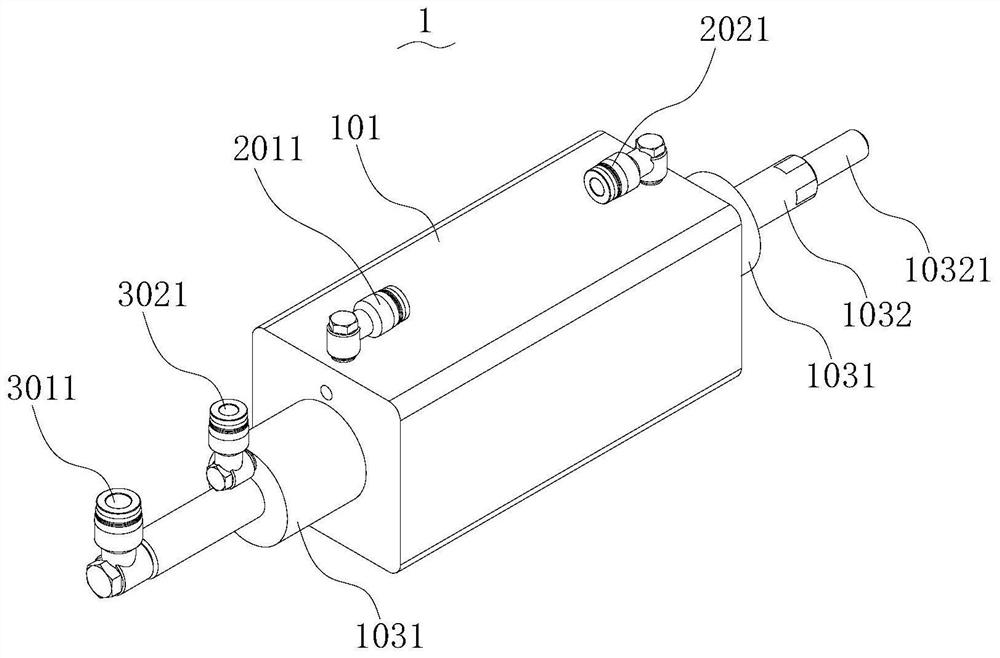
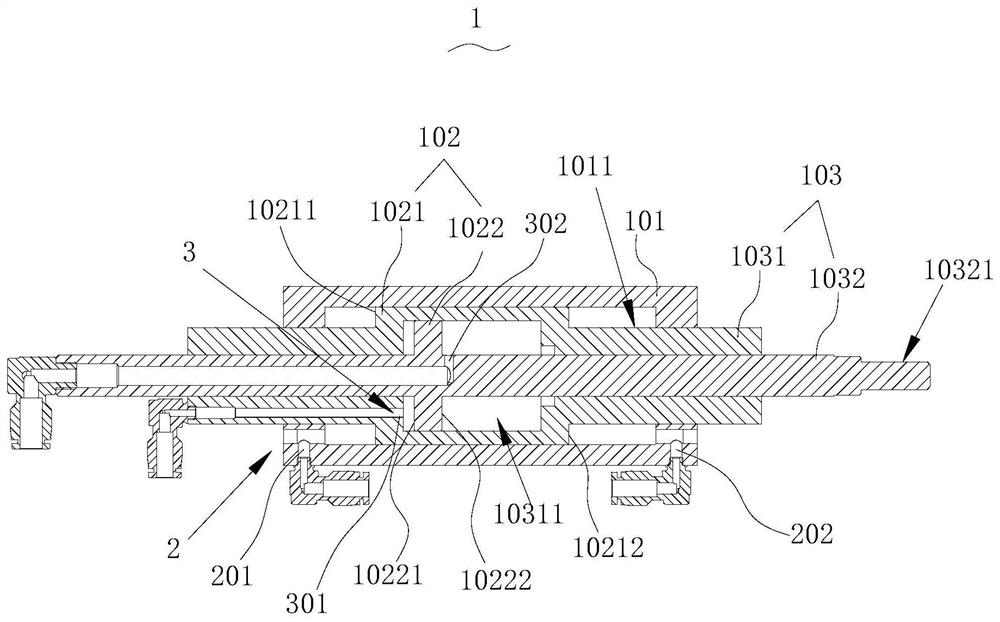
[0054] refer to Figure 1~3 , this embodiment discloses a differential pressure pneumatic telescopic cylinder 1, comprising a cylinder body 101, a piston 102 and a piston rod 103 connected to the piston 102, at least two piston rods 103 are provided, and each piston rod 103 is connected to a piston 102 , the cylinder body 101 is provided with a primary sliding chamber 1011, the piston rod 103 includes a primary telescopic rod 1031 and several secondary telescopic rods 1032, the piston 102 of the primary telescopic rod 1031 slides in the primary sliding chamber 1011, and the primary Telescopic rod 1031, several secondary telescopic rods 1032 are provided with secondary sliding cavity 10311, primary telescopic rod 1031, several secondary telescopic rods 1032 are nested successively, and the piston 102 of secondary telescopic rod 1032 is in the secondary Sliding in the stage sliding cavity 10311;

[0055] In the primary sliding chamber 1011, the piston 102 of the primary telesco...

Embodiment 2

[0067] refer to Figure 4 , this embodiment discloses another differential pressure pneumatic telescopic cylinder 1, based on embodiment 1, the differences between this embodiment and embodiment 2 are:

[0068] In this embodiment, the third ventilation hole 301 and the fourth ventilation hole 302 are both arranged on the primary telescopic rod 1031 , and the third ventilation hole 301 and the fourth ventilation hole 302 are respectively located on two sides of the second plug body 1022 .

[0069] Compared with Embodiment 1, the size of the primary telescopic rod 1031 in the radial direction is larger.

Embodiment 3

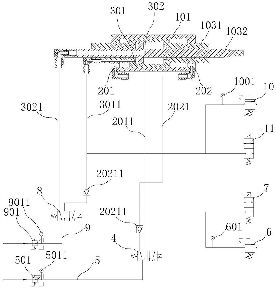
[0071] refer to Figure 5-7 , this embodiment discloses a differential pressure pneumatic clamp 12, which includes the differential pressure pneumatic telescopic cylinder 1 of the above embodiment, and also includes a clamp body 1201, a first jaw 1202, a second jaw 1203, a rack and pinion The transmission assembly 1204, the rack and pinion transmission assembly 1204 drives the first jaw 1202 and the second jaw 1203 to move toward each other or move away from each other, the cylinder body 101 of the differential pressure pneumatic telescopic cylinder 1 is fixed to the clamp body 1201, and the differential pressure telescopic The output end 10321 of the cylinder is connected with the first jaw 1202 or the second jaw 1203 , and the moving direction of the output end 10321 is parallel to the moving direction of the first jaw 1202 or the second jaw 1203 .

[0072] refer to Image 6, in this embodiment, the rack and pinion transmission assembly 1204 includes a driving gear 12041 an...


PUM


Abstract

The invention discloses a differential pressure type pneumatic clamp, and relates to the field of pneumatic clamps. According to the scheme, the differential pressure type pneumatic clamp comprises aclamp body, a first clamping jaw, a second clamping jaw and a gear and rack transmission assembly, and the gear and rack transmission assembly drives the first clamping jaw and the second clamping jawto move towards each other or away from each other; and the differential pressure type pneumatic clamp further comprises a differential pressure type pneumatic telescopic cylinder, a cylinder body ofthe differential pressure type pneumatic telescopic cylinder is fixed to the clamp body, an output end is connected with the first clamping jaw or the second clamping jaw, and the moving direction ofthe output end is parallel to the moving direction of the first clamping jaw or the second clamping jaw. The differential pressure type pneumatic telescopic cylinder can output forces of different magnitudes, so that the pneumatic clamp can output clamping forces of different magnitudes, different clamping forces can be used for clamping to-be-clamped parts of different rigidities, the situationthat the to-be-clamped parts are clamped to be flat due to the fact that the clamping force is too large or cannot be clamped due to the fact that the clamping force is too small is reduced, the clamping stability and reliability are improved, and the applicability is high.

Description

technical field [0001] The invention relates to the field of pneumatic clamps, in particular to a differential pressure pneumatic clamp. Background technique [0002] In the field of machining, there are all kinds of clamping tools, and pneumatic clamps are one of them. [0003] In the field of laser cutting, chucks and manipulators are common clamping tools. Take the manipulator as an example. Among the existing published patents, the Chinese patent application with the application number "201910864876.3" discloses the "manipulator", which includes the upper fixture. 5.9 and the lower fixture 5.8, the upper fixture 5.9 and the lower fixture 5.8 all include clamping blocks and clamping racks, the upper fixture 5.9 and the lower fixture 5.8 are arranged oppositely, and the clamping gear is driven to rotate by the clamping motor, and then the clamping gear drives the clamp The tightening rack moves, thereby driving the upper clamp and the lower clamp to move toward each other...

Claims


Application Information

Patent Timeline
Patent Type & Authority Applications(China)
IPC IPC(8): B25B5/00B25B5/16
CPCB25B5/00B25B5/16
Inventor 喻荣山常勇
Owner FOSHAN HONGSHI LASER TECH CO LTD
Why Eureka
Try Eureka