
Composite material base for aircraft

A technology for composite materials and aircraft, applied in the field of composite material bases, can solve problems such as weak interlayer strength, pull-out of steel wire nuts, failure of composite materials, etc., to prevent structural strength from decreasing, increase connection strength, and improve structural strength Effect

Inactive Publication Date: 2020-10-16
BEIJING INST OF ELECTRONICS SYST ENG
View PDF5 Cites 0 Cited by
  • Summary
  • Abstract
  • Description
  • Claims
  • Application Information

AI Technical Summary

Problems solved by technology

[0008] 1. The base made of composite materials has high strength in the direction of the single fiber layer, but the normal strength is small, that is, the strength between the fiber layers is weak, and it is easy to delaminate under load, etc. Happening
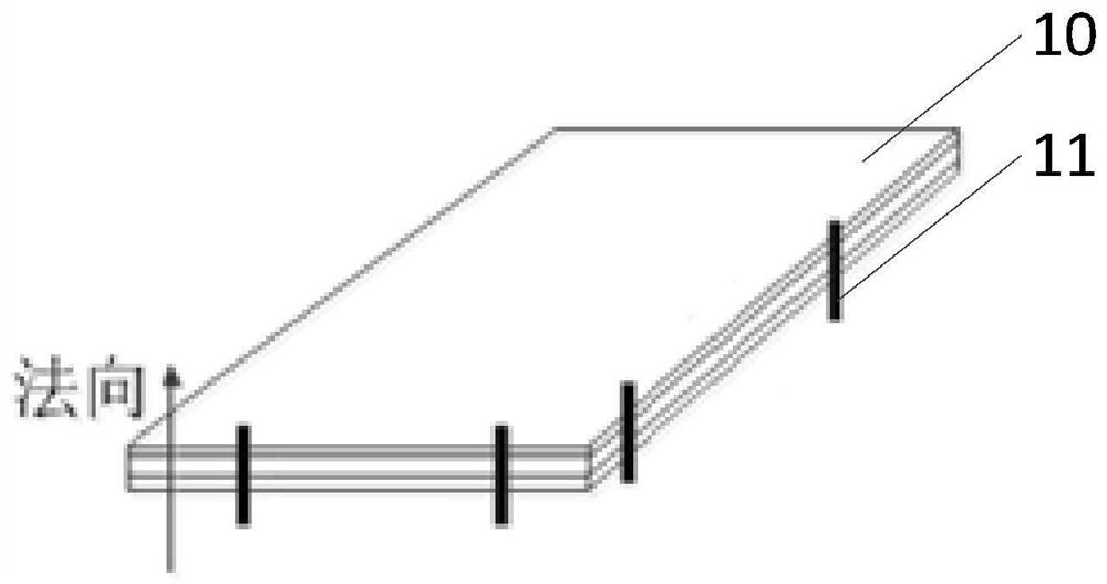
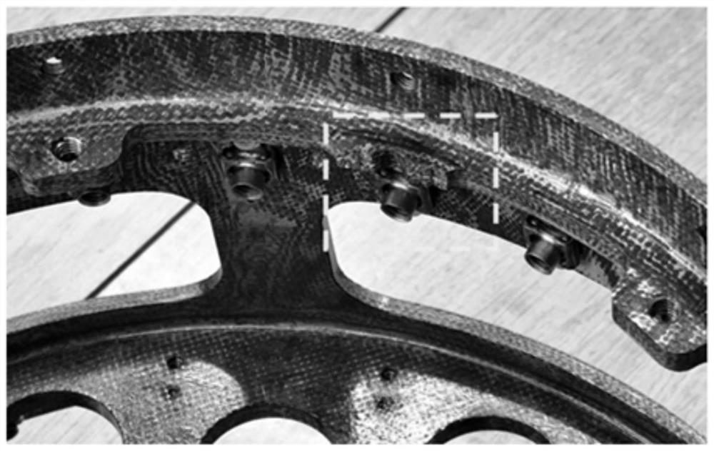
like figure 1 As shown, in the prior art, the normal strength of the base is enhanced by inserting the Z-Pin (normal steel pin 11) in the normal direction of the base surface 10, figure 1 The direction of the arrow in the figure is the normal direction of the base surface 10, but after the normal steel needle is inserted, the normal steel needle will cause local defects in the fiber layer, reducing the structure in the single fiber layer of the base structure. Strength, it is very easy to break the single fiber layer, specifically, such as figure 2 shown
[0009] 2. The base structure of the prior art generally includes a flange for installing equipment, and the equipment is installed in the middle of the flange through a cantilever. During the flight, under the action of vibration load, the equipment will have a large displacement response, which will affect normal operation of the equipment
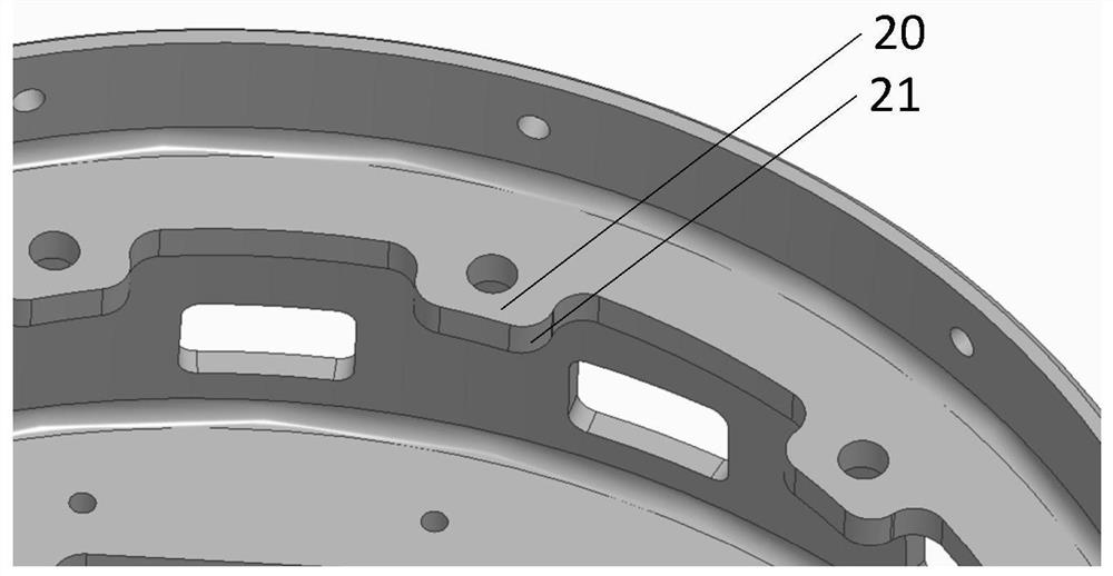
However, the fibers in the lug structure 20 with rounded corners 21 in the prior art are easily broken, resulting in a sharp drop in the strength of the lug structure 20
[0011] 4. In the prior art, it is usually necessary to install the equipment on the side wall of the base, but since the side wall of the base is an arc surface area with a narrow space, it is difficult to directly inlay the nuts on the supporting plate, so in the prior art, the supporting plate nuts are generally installed on the supporting plate. The position where the nut is screwed is provided with a wire screw sleeve for connection, but due to the weak interlayer strength of the base of the composite material, the wire screw sleeve is prone to problems such as pull-out, damage, and composite material failure during use.

Method used


Image

  • Composite material base for aircraft
  • Composite material base for aircraft
  • Composite material base for aircraft

Examples


Embodiment Construction

[0046] In order to make the purpose, technical solutions and advantages of the embodiments of the present invention more clear, the following will clearly and completely describe the technical solutions of the embodiments of the present invention in conjunction with the drawings of the embodiments of the present invention. Apparently, the described embodiments are some, not all, embodiments of the present invention. Based on the described embodiments of the present invention, all other embodiments obtained by persons of ordinary skill in the art without creative efforts shall fall within the protection scope of the present invention.

[0047] Unless otherwise defined, the technical terms or scientific terms used in the present invention shall have the usual meanings understood by those skilled in the art to which the present invention belongs. "First", "second" and similar words used in the present invention do not indicate any order, quantity or importance, but are only used ...


PUM


Abstract

The embodiment of the invention discloses a composite material base for an aircraft. The composite material base comprises a shell and a first bearing plate located in the shell and arranged in the circumferential direction of the inner side wall of the shell. The first bearing plate comprises a plurality of protruding parts protruding outwards, and each protruding part comprises a first through hole penetrating through the upper side surface and the lower side surface of the protruding part. The base further comprises fixing pieces arranged corresponding to the first through holes, and each fixing piece comprises a first cylinder part used for being embedded into the first through hole and a hollow first crimping part located at one end of the first cylinder part. When the first cylinderpart is embedded into the first through hole, the top surface of a first crimping part abuts against the bottom surface of the protruding part. The base provided by the embodiment of the invention caneffectively overcome the problems of lightness, rigidity and strength insufficiency of the composite material base in the base design, improve the structural strength between composite material layers and prevent the composite material layers from layering.

Description

technical field [0001] The invention relates to the technical field of aircraft, in particular to a composite material base for an aircraft. Background technique [0002] The base is an important component in aerospace products. The equipment in aerospace products is generally installed directly on the base, and the base is connected with the cabin of aerospace products to form an integral structure. [0003] The base used for aircraft generally has the following design requirements: [0004] 1. Strength requirements. Since the equipment of aerospace products is generally installed on the base with a cantilever, the installation base will be subject to a greater load when the aircraft is overloaded during flight, and the connecting parts and supporting parts of the base will be subject to a greater load , therefore, the design requirement for the base is that the base should not fail under severe working conditions such as cracks, breakage, and falling off; [0005] 2. Ri...

Claims


Application Information

Patent Timeline
Patent Type & Authority Applications(China)
IPC IPC(8): B64D47/00B64G1/22
CPCB64D47/00B64G1/22
Inventor 杨宁辛玲王大奎
Owner BEIJING INST OF ELECTRONICS SYST ENG
Learn More