Crushing equipment for corrugated paper recycling

A technology for crushing equipment and corrugated paper, applied in the field of corrugated paper recycling, which can solve the problems of easy injury and low efficiency of crushing operators

Active Publication Date: 2020-10-16
WUHAN INSTITUTE OF TECHNOLOGY
View PDF7 Cites 0 Cited by
  • Summary
  • Abstract
  • Description
  • Claims
  • Application Information

AI Technical Summary

Problems solved by technology

[0003] In the production process of corrugated cardboard, there will be a lot of leftovers. Usually the leftovers will be crushed and recycled, and the crushed recycling is generally done manually. Not only is the efficiency low, but also the crushing operators are vulnerable to injury.

Method used


Image

  • Crushing equipment for corrugated paper recycling

Examples


Embodiment 1

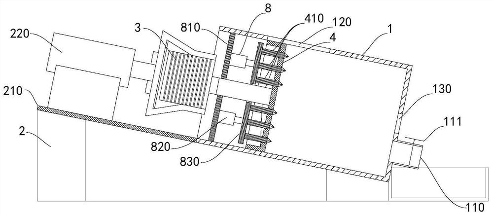
[0018] Example 1, such as figure 1 As shown, a crushing equipment for recycling corrugated paper includes a crushing barrel 1, a telescopic mechanism 2, a motor 3 and a crushing disc 4. The crushing barrel 1 is arranged obliquely. The crushing barrel 1 has a cylindrical inner cavity with an open upper end and a closed lower end. The crushing barrel The bottom of the barrel of 1 is provided with discharge port b110; the crushing disc 4 is placed in the inner cavity, and the wall surface of the crushing barrel 1 is provided with a feeding port 120 in the area between the crushing disc 4 and the bottom of the inner cavity; the output shaft of the motor 3 It is connected with the broken disc 4; the telescopic mechanism 2 is connected with the motor 3, and drives the motor 3 and the broken disc 4 to move in the inner cavity, so that the broken disc 4 is close to and away from the bottom of the inner cavity, and the broken disc 4 is close to the inner cavity The end face of the cavi...

Embodiment 2

[0019] Example 2, such as figure 1 As shown, the present embodiment is a further optimization carried out on the basis of embodiment 1, which is specifically as follows:

[0020] The telescoping mechanism 2 includes a base 210 and a hydraulic cylinder 220 , the hydraulic cylinder 220 is arranged on the base 210 , the crushing barrel 1 is arranged on the base 210 obliquely, and the piston rod of the hydraulic cylinder 220 is connected with the motor 3 .

Embodiment 3

[0021] Example 3, such as figure 1 As shown, the present embodiment is a further optimization carried out on the basis of embodiment 1 or 2, which is specifically as follows:

[0022] The crushing equipment for corrugated paper recycling also includes an adjustment mechanism 8, which is arranged on the output shaft of the motor 3 or on the inner wall of the crushing barrel 1, and the crushing disc 4 is provided with a via hole, and one end of the crushing tooth 410 is connected with the adjustment mechanism 8, The other end of the crushing tooth 410 extends to the bottom of the inner cavity through the hole, and is driven by the adjustment mechanism 8 to approach and stay away from the bottom of the inner cavity. A rubber ring is provided in the hole to prevent the slurry from passing through in the later pulping process. The gap between the crushing tooth 410 and the via hole is splashed out.


PUM

PropertyMeasurementUnit
lengthaaaaaaaaaa

Abstract

The invention relates to a crushing equipment for corrugated paper recycling. The crushing equipment comprises a crushing barrel, a telescopic mechanism, a motor and a crushing disc, the crushing barrel is obliquely arranged, the crushing barrel is provided with a cylindrical inner cavity with an opening in the upper end and a closed lower end, and a discharging opening b is formed in the barrel bottom of the crushing barrel; the crushing disc is arranged in the inner cavity, and a feeding port is formed in the area, between the crushing disc and the bottom of the inner cavity, of the wall face of the crushing barrel. An output shaft of the motor is connected with the crushing disc; the telescopic mechanism is connected with the motor and drives the motor and the crushing disc to move in the inner cavity, so that the crushing disc gets close to and away from the bottom of the inner cavity, and crushing teeth are arranged on the end face, close to the bottom of the inner cavity, of thecrushing disc. The invention has the beneficial effects that the whole crushing process is high in efficiency, crushing and pulping can be organically combined, and processing procedures are reduced.

Description

technical field [0001] The invention relates to the field of corrugated paper recycling, in particular to a crushing device for corrugated paper recycling. Background technique [0002] Corrugated paper is a plate made of liner paper and corrugated corrugated paper formed by corrugating rollers. It is generally divided into two types: single corrugated board and double corrugated board. [0003] In the production process of corrugated cardboard, there will be a lot of leftovers. Usually the leftovers will be crushed and recycled, and the crushed recycling is generally done manually. Not only is the efficiency low, but also the crushing operators are vulnerable to injury. Contents of the invention [0004] The technical problem to be solved by the present invention is to provide a crushing equipment for recycling corrugated paper, so as to overcome the above-mentioned deficiencies in the prior art. [0005] The technical solution of the present invention to solve the above...

Claims


Application Information

Patent Timeline
Patent Type & Authority Applications(China)
IPC IPC(8): D21B1/32D21B1/34
CPCD21B1/32D21B1/345D21B1/347Y02W30/64
Inventor 王大威吴江渝曾小平侯敏屈丹
Owner WUHAN INSTITUTE OF TECHNOLOGY
Why Eureka
Try Eureka