Buckling-shearing metal damper applied to shock isolation layer
A metal damper, shear type technology, applied in the direction of earthquake resistance, building type, building components, etc., can solve the problem of difficult to meet the large deformation demand of the seismic isolation layer, the deformation capacity is small, etc., to prevent harm to human health and pollution of the environment. , The effect of strong deformation ability and low price
- Summary
- Abstract
- Description
- Claims
- Application Information
AI Technical Summary
Problems solved by technology
Method used
Image

Examples
Embodiment 1
[0022] Example 1: Arranged on both sides of the shock-isolation support:
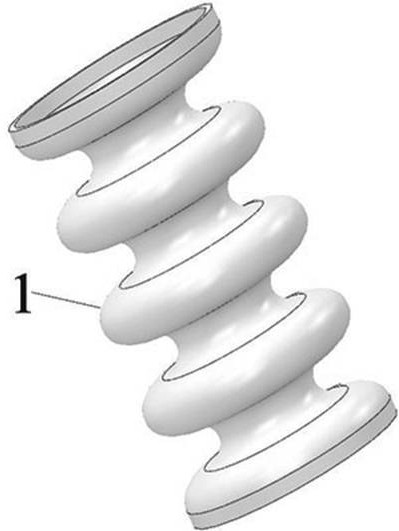
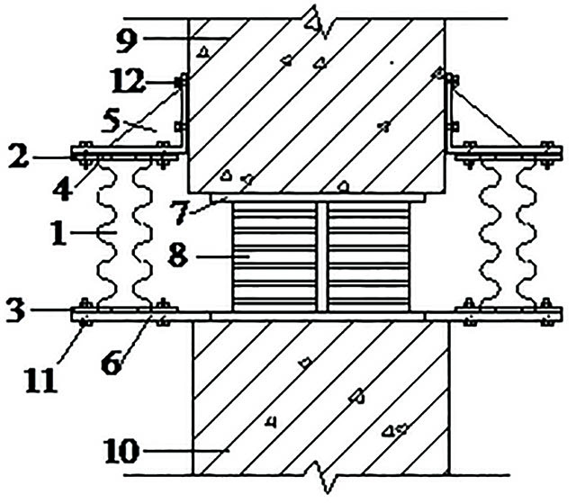
[0023] Such as figure 1 As shown, a buckling-shear type metal damper includes a corrugated tube 1, an upper connecting plate 2, a lower connecting plate 3, an annular brace 4, an L-shaped connecting piece 5, etc.;
[0024] (1) Clamp one end of the corrugated tube 1 between the upper connecting plate 2 and the annular support plate 4, such as Figure 5 As shown, the edge of the corrugated tube 1 is flush and coplanar with the upper surfaces of the upper connecting plate 2 and the annular support plate 4, and the three are welded and fixed at the splicing position of the upper surfaces. Similarly, the other end of the corrugated tube 1 is welded and fixed to the lower connecting plate 3 and the annular support plate 4 to form a damper component;
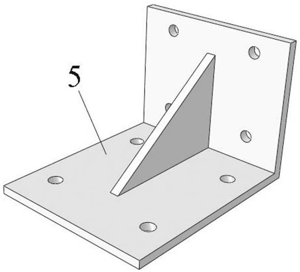
[0025] (2) Fix the L-shaped connector 5 on the upper pier 9 through the embedded bolt 12 . When pouring the upper pier 9, connecting bolts should be embedded...
Embodiment 2
[0029] Embodiment 2: Arranged at the bottom of the beam on the seismic isolation layer:
[0030] The buckling-shear type metal damper can be directly installed on the bottom of the seismic isolation beam 14 .
[0031] When the size of the damper is small, such as Figure 9 As shown, the upper connecting plate 2 of a plurality of damper parts arranged side by side is fixed on the bottom of the seismic isolation beam 14 through embedded bolts 12, and the lower connecting plate 3 of the damper part is connected to the foundation beam 15 through a steel connector 13 Fixed connection, the lower connecting plate 3 and the section steel connector 13 are connected and fixed by high-strength bolts 11 , and the section steel connector 13 and the foundation beam 15 are connected and fixed by embedded bolts 12 .
[0032] When the size of the damper is large, such as Figure 10 As shown, the upper connecting plate 2 of the damper is fixed to the bottom of the seismic isolation beam 14 th...
Embodiment 3
[0034] Example 3: Seismic isolation layers arranged in other seismic isolation systems:
[0035] The buckling-shear type metal damper proposed by the present invention can also be used in combination with other shock-isolating devices 16, such as friction-slip shock-isolation bearings, friction pendulum shock-isolation bearings, and the like. In the same way, by repeating the four operation steps in Example 1, the dampers can be arranged on one side, both sides, and around other shock-isolating devices 16; by repeating the operation in Example 2, the dampers can be arranged on other isolation devices 16. The bottom of the seismic isolation floor beam of the seismic system, such as Figure 11 shown. A composite seismic isolation system composed of buckling-shear metal dampers and friction-slip isolation bearings or friction pendulum isolation bearings. The damper can provide high damping and lateral force resistance for the isolation layer, and exert energy dissipation, limit...
PUM
 Abstract
Description
Claims
Application Information
 - R&D
- Intellectual Property
- Life Sciences
- Materials
- Tech Scout
- Unparalleled Data Quality
- Higher Quality Content
- 60% Fewer Hallucinations
Browse by: Latest US Patents, China's latest patents, Technical Efficacy Thesaurus, Application Domain, Technology Topic, Popular Technical Reports.
© 2025 PatSnap. All rights reserved.Legal|Privacy policy|Modern Slavery Act Transparency Statement|Sitemap|About US| Contact US: help@patsnap.com