
Floor block and manufacturing method thereof

A production method and technology of floor boards, which are applied to floors, buildings, building structures, etc., can solve the problems of honeycomb substrate disintegration, easy damage, and inability to achieve impact resistance, and achieve fast curing speed, saving usage, and excellent resistance. The effect of compressive and flexural properties

Pending Publication Date: 2020-10-16
SHANGHAI XINGYE MATERIALS TECH CO LTD
View PDF1 Cites 0 Cited by
  • Summary
  • Abstract
  • Description
  • Claims
  • Application Information

AI Technical Summary

Problems solved by technology

There is a hollow structure between many parts of the upper stone panel and the lower honeycomb substrate. When this part of the upper stone panel is subjected to a downward impact, it is easy to be damaged, and the "shock resistance" performance claimed in the patent specification cannot be achieved.
[0005] 2. Conventional adhesives need to be exposed to the environment in a large area to cure quickly. To ensure the bonding strength between the stone panel and the honeycomb substrate, the adhesive must be applied between the stone panel and the honeycomb substrate before curing
However, the bonding process with the help of thermosetting or hot-melt adhesives requires high temperature, and the structural layers in the existing honeycomb panels are bonded by hot-melt adhesives (hot-melt adhesive films) that cannot withstand high temperatures. Connected together, if the stone panel and honeycomb substrate are bonded with thermosetting or hot-melt adhesive, it will cause the honeycomb substrate to disintegrate at high temperature

Method used


Image

  • Floor block and manufacturing method thereof
  • Floor block and manufacturing method thereof
  • Floor block and manufacturing method thereof

Examples


Embodiment 1

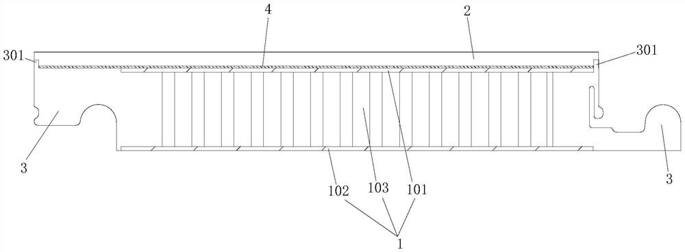
[0058] Figure 1 to Figure 5 A preferred embodiment of the floorboard of the present application is shown. The same structure as the floorboard mentioned in the background art is that the floorboard also includes a honeycomb substrate 1 and a panel 2 that is attached to and fixed on the upper surface of the honeycomb substrate. .

[0059] The difference from traditional honeycomb panels is:

[0060] In this embodiment, the honeycomb substrate 1 includes: a honeycomb core layer 103, an upper plate body 101 bonded and fixed on the upper surface of the honeycomb core layer by a thermosetting adhesive (rather than a hot-melt adhesive), and a thermosetting adhesive ( The lower plate body 102 is bonded and fixed on the lower surface of the honeycomb core layer by using non-hot-melt adhesives. The panel 2 is bonded and fixed on the upper surface of the upper plate body 101 by a thermosetting adhesive.

[0061] When crafting this floor block:

[0062] First, the upper surface of t...

Embodiment 2

[0079] Figure 6 and Figure 7 Another preferred embodiment of the floorboard of the present application is shown, the structure of the floorboard is basically the same as that of Embodiment 1, the main difference is only in:

[0080] The panel 2 is bonded and fixed to the upper surface of the upper plate body 101 by means of a hot-melt adhesive (instead of the thermosetting adhesive in Embodiment 1).

[0081] Further, the panel 2 and the upper panel body 101 of the honeycomb substrate 1 are bonded and fixed by the hot melt adhesive film 6 sandwiched between them.

[0082] refer to Figure 6 As shown, when crafting this floorboard:

[0083] First, the upper surface of the lower plate body 102 and the lower surface of the upper plate body 101 are coated with a liquid thermosetting adhesive, and the honeycomb core layer 103 is arranged between the lower plate body 102 and the upper plate body 101. 102 and the upper plate 101 apply a clamping force close to each other to sque...

Embodiment 3

[0089] refer to Figure 8 to Figure 12 As shown, the structure of the floorboard of this embodiment is basically the same as that of Embodiment 1. The main difference is that the honeycomb core layer of the honeycomb substrate in this embodiment adopts another structure, thereby improving the honeycomb core layer 103 and the upper plate body 101 and The bonding area and bonding strength of the lower plate body 102 reduce the possibility of the upper and lower plate bodies detaching from the honeycomb core layer as follows:

[0090]The honeycomb core layer 103 is composed of a very thin metal sheet 1031 and punching the metal sheet to integrally form a plurality of downwardly protruding punching protrusions 1032 on the metal sheet. The upper surface 1031a of the metal sheet 1031 is attached to and bonded to (the lower surface of) the upper plate body 101 , and the lower surface 1032a of the punching protrusion 1032 is attached to and bonded to (the upper surface of) the lower p...


PUM

PropertyMeasurementUnit
thicknessaaaaaaaaaa

Abstract

The invention relates to a floor block and a manufacturing method thereof. The floor block comprises a honeycomb base plate and a panel fixedly attached to the surface of the honeycomb base plate. Thehoneycomb base plate comprises a honeycomb core layer, an upper plate body and a lower plate body. The upper plate body is fixedly bonded to the upper surface of the honeycomb core layer through a thermosetting adhesive. The lower plate body is fixedly bonded to the lower surface of the honeycomb core layer through a thermosetting adhesive. The panel is fixedly bonded to the upper surface of theupper plate body through a thermosetting or hot-melting adhesive. The floor block really has both abrasion resistance and beauty of the upper panel and pressure and impact resistance of the lower honeycomb base plate, manufacturing efficiency of the floor block is promoted, and thus floor blocks can be produced industrially at a large scale.

Description

technical field [0001] The present application relates to the field of floors, in particular to a floor board and a manufacturing method thereof. Background technique [0002] The Chinese Utility Model Patent No. CN200420108932.X discloses a floor board composed of a honeycomb substrate and a stone panel. This kind of floor board with composite structure has both the wear resistance and aesthetics of stone and the compression and impact resistance of honeycomb panels. However, this patent document only records that the stone panel on the upper layer of the composite floor board is bonded and fixed on the upper surface of the lower honeycomb board by means of a special adhesive, and does not specify what kind of adhesive the special adhesive is, let alone specify The bonding process of stone panels and honeycomb substrates. [0003] If conventional adhesives and conventional methods are used to bond the stone panels and honeycomb substrates in the above-mentioned patent doc...

Claims


Application Information

Patent Timeline
Patent Type & Authority Applications(China)
IPC IPC(8): E04F15/02E04F15/04E04F15/08E04F15/10
CPCE04F15/02E04F15/02038E04F15/041E04F15/082E04F15/105E04F15/107E04F2201/0146E04F2201/026E04F2201/042E04F2201/044
Inventor 高峰刘在祥陈艳凤蔡园丰王兵牛争艳
Owner SHANGHAI XINGYE MATERIALS TECH CO LTD
Learn More