Solid rocket engine shell, solid rocket engine and manufacturing method thereof
A technology for engine shells and solid rockets, which is applied to rocket engine devices, machines/engines, mechanical equipment, etc. It can solve problems such as inability to perform real-time in-situ monitoring and early warning, and solid rocket engine monitoring lag, and achieve enhanced engine state prediction ability, reducing the difficulty of inspection and fault identification, and ensuring safety and stability
- Summary
- Abstract
- Description
- Claims
- Application Information
AI Technical Summary
Problems solved by technology
Method used
Image

Examples
Embodiment 1
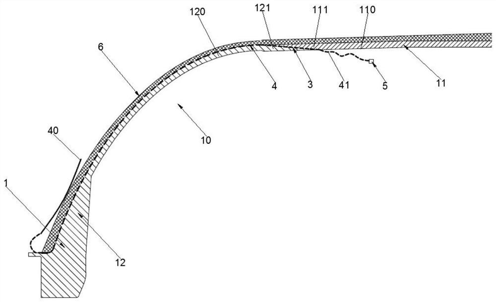
[0057] see figure 1 As shown, Embodiment 1 of the present application provides a solid rocket motor casing, which can solve the problems in the related art that the monitoring of the interior of the solid rocket motor lags behind and that real-time in-situ monitoring and early warning cannot be performed.
[0058] A solid rocket motor housing provided in Example 1 of the present application includes a thermal insulation structure 1, a winding layer 6, a plurality of optical fibers 4 and a plurality of sensors 5, and the thermal insulation structure 1 has a charging space for accommodating propellant grains 2 10, and the thermal insulation structure 1 is provided with an optical path channel 3 extending along the circumferential direction of the thermal insulation structure 1. The optical path channel 3 is the space occupied by the optical fiber 4 itself. After the optical fiber 4 enters the optical path channel 3, the optical path channel 3 is closed. 4 and the thermal insulat...
Embodiment 2
[0065] The basic content of embodiment 2 of the present application is the same as embodiment 1, and difference is:
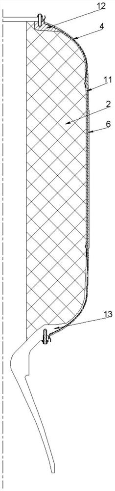
[0066] see figure 2 As shown, the optical path channel 3 is formed by the end faces of the column section 11 and the rear head section 13 connected to each other, and the embedded end 41 extends along the generatrix direction of the rear head section 13 to be embedded in the optical path channel 3 . The optical fiber 4 penetrates into the heat insulation structure 1 from the junction of the rear head section 13 and the column section 11, and the junction of the rear head section 13 and the column section 11 is not in contact with the high-temperature gas until the engine is near the end of operation, which has a short exposure time , high reliability and long test time range. However, since the manufacturing process of the heat insulating structure 1 is to manufacture the front head section 12 first, it is more practical that the optical path channel 3 is for...
Embodiment 3
[0068] The basic content of embodiment 3 of the present application is the same as embodiment 1, and the difference is:
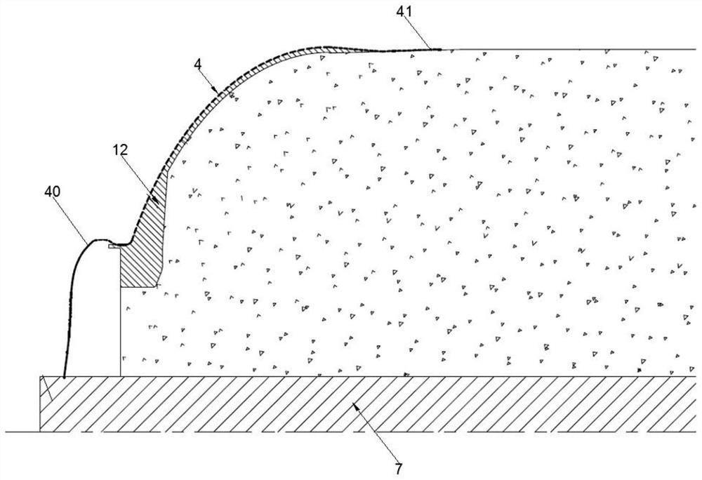
[0069] see figure 2 As shown, the optical path channel 3 is formed by the end face connecting the column section 11 and the front head section 12, and the end surface connecting the column section 11 and the rear head section 13, and the embedded end 41 extends along the generatrix direction of the front head section 12 To be embedded in the optical path channel 3 formed by the column section 11 and the front head section 12, and the embedded end 41 extends along the generatrix direction of the rear head section 13 to be embedded in the rear head section 13 and the front head section 12 to form within channel 3 of the optical path. The form of embedding the front head section 12 and the rear head section 13 inside the thermal insulation structure 1 can greatly increase the success rate of the optical fiber 4 embedding, and can monitor both sections of the...
PUM
 Abstract
Description
Claims
Application Information
 - R&D
- Intellectual Property
- Life Sciences
- Materials
- Tech Scout
- Unparalleled Data Quality
- Higher Quality Content
- 60% Fewer Hallucinations
Browse by: Latest US Patents, China's latest patents, Technical Efficacy Thesaurus, Application Domain, Technology Topic, Popular Technical Reports.
© 2025 PatSnap. All rights reserved.Legal|Privacy policy|Modern Slavery Act Transparency Statement|Sitemap|About US| Contact US: help@patsnap.com