
A fluid discharge device

An emission device and fluid technology, which is applied in jet propulsion devices, rocket engine devices, machines/engines, etc., can solve the problems of slow emission speed, hidden dangers, and safety, and achieve leakage prevention, high safety, and sealing performance. Effect

Active Publication Date: 2021-03-09
BEIJING INST OF AEROSPACE TESTING TECH
View PDF9 Cites 0 Cited by
  • Summary
  • Abstract
  • Description
  • Claims
  • Application Information

AI Technical Summary

Problems solved by technology

[0004] Therefore, the technical problem to be solved by the present invention is to overcome the defects of the low-temperature propellant and other fluids in the prior art that directly impact the ground when they are discharged, have potential safety hazards, and have a slow discharge speed, thereby providing a method that avoids directly impacting the ground when the fluid is discharged. Fluid discharge device that reduces potential safety hazards and increases discharge speed

Method used


Image

  • A fluid discharge device
  • A fluid discharge device
  • A fluid discharge device

Examples


Embodiment Construction

[0032] The technical solutions of the present invention will be clearly and completely described below in conjunction with the accompanying drawings. Apparently, the described embodiments are some of the embodiments of the present invention, but not all of them. Based on the embodiments of the present invention, all other embodiments obtained by persons of ordinary skill in the art without making creative efforts belong to the protection scope of the present invention.

[0033] In addition, the technical features involved in the different embodiments of the present invention described below may be combined with each other as long as there is no conflict with each other.

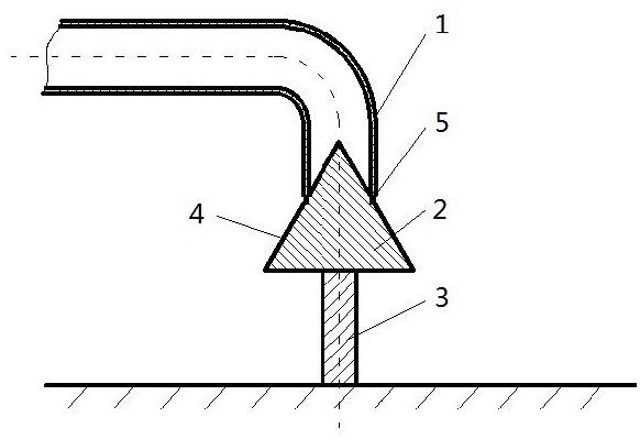
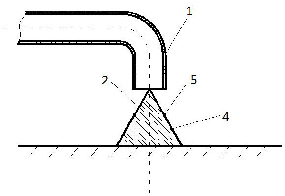
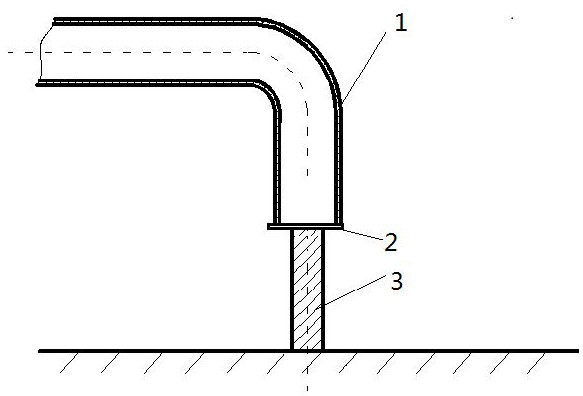
[0034] Such as figure 1 and 2 A specific implementation of the fluid discharge device shown, the fluid in this embodiment is cryogenic propellant for launch vehicles, such as liquid hydrogen or liquid methane, including a discharge pipe 1 , a flow guide structure 2 and a support structure 3 .

[0035] The d...


PUM


Abstract

The present invention relates to the technical field of fluid emergency discharge, in particular to a fluid discharge device, comprising: a discharge pipe with a fluid inlet and a fluid outlet; The fluid in the discharge pipe flows out according to a predetermined path, and the first position is blocked with the fluid outlet of the discharge pipe and the second position is opened to guide the fluid in the discharge pipe to flow out along the flow guide surface. Position; supporting structure, which is arranged corresponding to the flow guiding structure, and provides sufficient force to support the flow guiding surface when the flow guiding structure is in the second position. The invention provides a fluid discharge device which avoids the direct impact on the ground when the fluid is discharged, reduces potential safety hazards and improves the discharge speed.

Description

technical field [0001] The invention relates to the technical field of fluid emergency discharge, in particular to a fluid discharge device. Background technique [0002] Throughout the history of aerospace development, it can be seen that the pace of human space exploration and the development of cryogenic propellant engines are basically the same. Since the 1950s, continuous breakthroughs in high-thrust liquid oxygen kerosene engine and hydrogen-oxygen engine technology have supported the launch and application of iconic spacecraft such as space shuttles and space stations. At present, in terms of the active power of the launch vehicle, the two are still considered to be the optimal energy combination. On the other hand, in terms of reusable vehicle power, the liquid oxygen methane engine stands out because of its relatively high specific impulse, less coking in the combustion process, low cost, and good regenerative cooling performance. At the same time, low-temperature...

Claims


Application Information

Patent Timeline
Patent Type & Authority Patents(China)
IPC IPC(8): F02K9/60
CPCF02K9/60
Inventor 罗天培岳广涛张家仙王相成周芳刘瑞敏喻闯闯魏仁敏吴薇梵李茂张佳
Owner BEIJING INST OF AEROSPACE TESTING TECH
Learn More