Vacuum waste heat steam boiler

A waste heat steam and boiler technology, applied in steam boilers, steam boiler accessories, steam boiler components, etc., can solve the problems of difficult control, large energy consumption, excessive power consumption, etc., to reduce boiler volume and service life long effect

Pending Publication Date: 2020-10-16
王新正
View PDF0 Cites 0 Cited by
  • Summary
  • Abstract
  • Description
  • Claims
  • Application Information

AI Technical Summary

Problems solved by technology

[0008] The purpose of the present invention is to provide a vacuum boiler using waste heat to solve the shortcomings of the above-mentioned existing vacuum boilers, such as high energy consumption, difficult control, and only hot water output, as well as excessive power consumption of the existing electric steam boilers. Evaporate in the furnace to produce low-temperature and low-pressure steam that can be precisely controlled by electric heating steam boiler

Method used


Image

  • Vacuum waste heat steam boiler

Examples


Embodiment Construction

[0035] The present invention will be further described below in conjunction with embodiment (accompanying drawing).

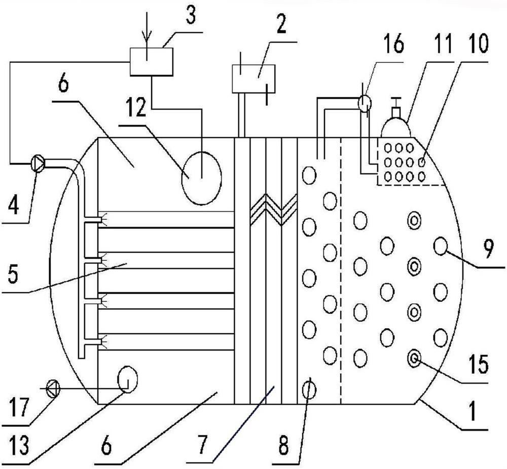
[0036] Such as figure 1 As shown, the vacuum waste heat steam boiler of the present invention includes a boiler casing 1 connected with a vacuum pump 2 capable of withstanding a vacuum degree of <400 Pa, a warm water evaporation chamber 5, a water baffle 7, and a second evaporation chamber sequentially arranged in the boiler casing 8. The high-temperature heating chamber 9 and the steam storage chamber 10 located above the side of the high-temperature heating chamber 9; in the middle of the warm water evaporation chamber 5, an evaporator composed of several evaporation tubes arranged in a longitudinal direction is arranged, and a communication channel is arranged above the evaporator. The waste heat and warm water inlet 12 of the boiler water distribution device 3 is provided with a waste heat and warm water outlet 13 below the evaporator; one end of several ev...


PUM


Abstract

The invention relates to a vacuum waste heat steam boiler which is characterized by comprising a boiler housing, connected to a vacuumizer, capable of bearing a vacuum degree which is lower than 400 Pa, a warm water evaporation chamber, a water baffle plate, a second evaporation chamber and a high-temperature heating chamber successively arranged in the boiler housing and a steam storage chamber located on the lateral upper side of the high-temperature heating chamber. An evaporator formed by a plurality of longitudinally arranged evaporation tubes is arranged in the middle of the warm water evaporation chamber 5, a waste heat warm water inlet communicating to a boiler water distributing device is formed above the evaporator and a waste heat warm water outlet is formed below the evaporator. Spray heads connected to a water outlet of an evaporative water pressure pump are arranged at one ends of the evaporation tubes forming the evaporator, and the evaporative water pressure pump communicates to the boiler water distributing device; the high-temperature heating chamber is provided with a hot water exchanger; the second evaporation chamber and the steam storage chamber separately communicate to an internal vacuumizer through pipelines; and a steam distributing valve is arranged on the top of the steam storage chamber.

Description

technical field [0001] The invention relates to a vacuum waste heat steam boiler which evaporates warm waste hot water in a vacuum cylinder, and the evaporated steam is heated to become high-temperature and high-pressure steam. Background technique [0002] The full name of the vacuum boiler is a vacuum phase change boiler, which forms a negative pressure vacuum environment inside the closed furnace body. The heat medium water is filled in the body, and the heat medium water is heated by combustion or other methods. The heat medium water is heated to generate steam, and the steam heats the water in the heat exchanger tube through condensation heat exchange to realize hot water supply. Vacuum filtration heat direction: oil, natural gas, gas, electricitycombustion (electric conversion heat) → boiled steam condensation heat exchange → heat exchanger → heat conduction → water. [0003] The working principle of the vacuum boiler: Utilizing the low boiling point of water in a ...

Claims


Application Information

Patent Timeline
IPC IPC(8): F22B1/28F22B31/08F22B37/42F22B37/00
CPCF22B1/28F22B31/08F22B37/00F22B37/42
Inventor 王新正娄开立娄伟楼雪薇吴钢田莉莉
Owner 王新正
Why Eureka
Try Eureka