Supercharge Your Innovation With Domain-Expert AI Agents!

Humidity adjusting device and method using chilled water for reheating

A technology for chilled water and chilled water systems, which is used in household heating, heating methods, household heating, etc., can solve the problems of complex systems and high overall energy consumption, simplify energy pipelines or systems, improve energy-saving efficiency, reduce effect used

Inactive Publication Date: 2020-10-16
博纳环境设备(太仓)有限公司
View PDF5 Cites 1 Cited by
  • Summary
  • Abstract
  • Description
  • Claims
  • Application Information

AI Technical Summary

Problems solved by technology

[0006] Therefore, the technical problem to be solved by the present invention is to overcome the problems of complex system and high overall energy consumption in the prior art, so as to provide a humidity control device that uses chilled water for reheating with simple system and low overall energy consumption and method

Method used


Image

  • Humidity adjusting device and method using chilled water for reheating
  • Humidity adjusting device and method using chilled water for reheating
  • Humidity adjusting device and method using chilled water for reheating

Examples


Embodiment 1

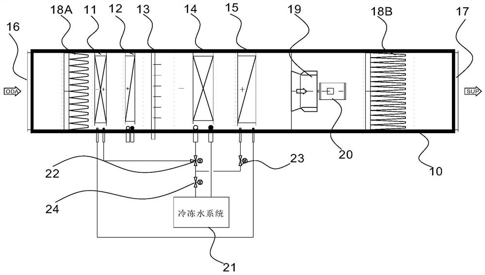
[0026] Such as image 3 and Figure 4 As shown, this embodiment provides a humidity control device using chilled water for reheating, including a first heat exchanger 11, a second heat exchanger 12, a humidifier 13, a third heat exchanger 14 and a fourth heat exchanger The air flows into the first heat exchanger 11, the second heat exchanger 12, the humidifier 13, the third heat exchanger 14 and the fourth heat exchanger 15 sequentially through the air inlet 16, and is discharged through the air outlet 17. The water inlet channel of the third heat exchanger 14 is connected to the chilled water system 21, and the water outlet channel of the third heat exchanger 14 is connected to the water inlet channel of the first heat exchanger 11 through the first valve 22, so The water outlet channel of the first heat exchanger 11 is connected to the water inlet channel of the fourth heat exchanger 15 , and the water outlet channel of the fourth heat exchanger 15 is connected to the chill...

Embodiment 2

[0040] Such as image 3 As shown, this embodiment provides a humidity control method for reheating with chilled water, using the humidity control device for reheating with chilled water described in Implementation 1 to adjust the temperature and humidity of the air, including step S1: The low-temperature chilled water in the water system 10 performs heat exchange, so that the low-temperature chilled water becomes medium-temperature chilled water, and the medium-temperature chilled water is used to perform the first heat exchange on the air to cool down the air, and the flow rate of the medium-temperature chilled water is controlled to make the medium-temperature After the chilled water has undergone heat exchange, high-temperature chilled water is discharged; step S2: perform a second heat exchange on the cooled air to heat up the air, and perform humidification treatment on the heated air; step S3: utilize the low temperature in the chilled water system 10 The chilled water p...


PUM


Abstract

The invention relates to a humidity adjusting device and method using chilled water for reheating. The humidity adjusting device comprises a first heat exchanger, a second heat exchanger, a humidifier, a third heat exchanger and a fourth heat exchanger, wherein air sequentially flows into the first heat exchanger, the second heat exchanger, the humidifier, the third heat exchanger and the fourth heat exchanger through an air inlet, and is exhausted through an air outlet, a water inlet channel of the third heat exchanger is connected with a chilled water system, a water outlet channel of the third heat exchanger is connected to a water inlet channel of the first heat exchanger through a first valve, a water outlet channel of the first heat exchanger is connected to a water inlet channel ofthe fourth heat exchanger, and a water outlet channel of the fourth heat exchanger is connected to the chilled water system through a second valve. The humidity adjusting device has the advantages ofbeing simple in structure and low in overall energy consumption.

Description

technical field [0001] The invention relates to the technical field of air conditioning systems, in particular to a humidity control device and method for reheating with chilled water. Background technique [0002] At present, in order to control the relative humidity in summer, many air-conditioning systems, especially in the areas south of the Yangtze River, often use fresh air to dehumidify at low temperature and then use various heat sources for reheating. This method of temperature and humidity adjustment not only consumes a lot of energy, but also the system It is also relatively complicated. [0003] Taking electronic clean workshops as an example, electronic components are entering the era of a new generation of components with new electronic components as the main body. In recent years, China's electronics industry has continued to grow at a high speed, driving the strong development of the electronic components industry. China has become the world's production bas...

Claims


Application Information

Patent Timeline
IPC IPC(8): F24F5/00F24F3/14F24F3/153F24F3/16F24F13/28F24F13/30F24F11/84F24F11/89
CPCF24F3/14F24F3/153F24F5/0017F24F13/28F24F13/30F24F11/84F24F11/89Y02E60/14
Inventor 魏鹏峰徐方敏苏卫兵谢娟童小英姚春鸣
Owner 博纳环境设备(太仓)有限公司
Features
  • R&D
  • Intellectual Property
  • Life Sciences
  • Materials
  • Tech Scout
  • Unparalleled Data Quality
  • Higher Quality Content
  • 60% Fewer Hallucinations
Learn More