Passive steel containment heat export system

A technology of steel containment and heat extraction, applied in the field of nuclear power plant reactor safety systems, can solve the problems of limited contact area of ​​heat exchanger 3, weakening the ability of steam condensation and heat transfer, reducing heat exchange and cooling efficiency, etc. Effective cooling time, high natural circulation ability, the effect of reducing resistance

Pending Publication Date: 2021-11-02
CHINA NUCLEAR POWER ENG CO LTD
View PDF2 Cites 0 Cited by
  • Summary
  • Abstract
  • Description
  • Claims
  • Application Information

AI Technical Summary

Problems solved by technology

For example, in the AP1000 scheme, the cooling water is directly lost to the environment after flowing through the outer wall of the containment, and the containment can no longer be cooled.
At the same time, considering the capacity limitation of the top water tank 2, the passive containment cooling system can only be effective for 72 hours
Another example is the passive containment heat export system disclosed in ZL201110437864.6. On the one hand, the heat exchanger 3 is located in the containment, and the local accumulation of non-condensable gas near the heat exchanger 3 will weaken the ability of steam to condense and exchange heat; Due to the limitation of the layout space, the contact area of ​​the heat exchanger 3 is limited, which affects the further improvement of the heat exchange power; in addition, the cooling water tank 2 arranged outside the containment increases the number of penetrations, while the cooling water tank 2 arranged inside the containment The failure of the heat exchanger 3 will also introduce an additional risk of containment flooding
ZL201410371100.5 discloses a solution for the external concrete pool of the steel containment. In order to realize the submersion of the containment, a concrete pool structure needs to be built outside the containment. For water reactor power plants, the construction difficulty and cost are relatively high; and because the water in the pool cannot flow, it is easy to form thermal stratification and reduce the overall heat exchange and cooling efficiency

Method used


Image

  • Passive steel containment heat export system
  • Passive steel containment heat export system
  • Passive steel containment heat export system

Examples


Embodiment Construction

[0029] The present invention will be further described below in conjunction with the accompanying drawings and embodiments.

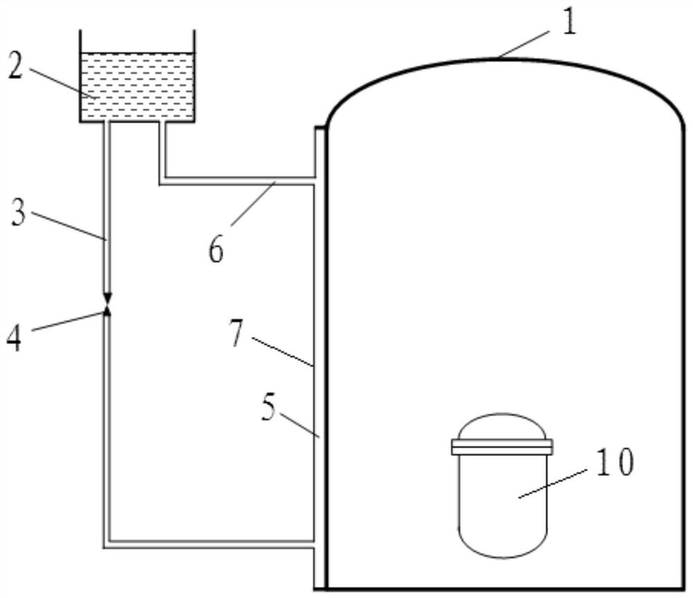
[0030] Such as image 3 , Figure 4 As shown, a passive steel containment heat extraction system provided by the present invention includes a cooling cover 7 arranged on the side wall of the containment vessel 1 of the reactor and the containment vessel 1 to form a closed annular cavity 5 together. The cooling cover 7 There is a cooling water circuit on the top, when the containment vessel 1 needs to cool down, the cooling water circuit can inject cooling water into the annular cavity 5 from the bottom of the cooling cover 7 in a passive way (depending on gravity), and the annular cavity 5 sucks The heated cooling water can flow back into the cooling water circuit from the top of the cooling cover 7 in a passive way (depending on the gravity pressure head formed by the fluid density difference); the material of the containment vessel 1 is stainless ste...


PUM


Abstract

The invention belongs to the technical field of nuclear power plant reactor safety systems, and particularly relates to a passive steel containment heat export system, which is characterized in that a cooling cover (7) is arranged on the side wall of a containment (1) of a reactor and forms a closed annular cavity (5) with the containment (1), a cooling water loop is arranged on the cooling cover (7), the cooling water loop can inject cooling water into the annular cavity (5) from the bottom of the cooling cover (7) in a passive mode, the cooling water absorbing heat in the annular cavity (5) can flow back into the cooling water loop from the top of the cooling cover (7) in a passive mode, and the containment (1) is made of stainless steel. According to the invention, dependence of a traditional active safety system on a safety-level power supply is eliminated, high natural circulation capacity and heat removal capacity are achieved, and the capacity of relieving accident consequences for a long time without intervention after an accident is provided.

Description

technical field [0001] The invention belongs to the technical field of nuclear power plant reactor safety systems, and in particular relates to a passive steel containment heat export system. Background technique [0002] The containment vessel is the last containment barrier for light water reactor nuclear power plants to prevent a large amount of radioactive fission products from the core from being released to the external environment. Under accident conditions in nuclear power plants, a large amount of high-temperature fluid (water and steam) will be released from the reactor cooling circuit into the containment space, causing a significant increase in temperature and pressure, thereby threatening the integrity of the containment structure. [0003] Traditional pressurized water reactor nuclear power plants use active containment sprinkler system to reduce the pressure and temperature of the containment, but this method cannot cope with the over-design basis condition of...

Claims


Application Information

Patent Timeline
Patent Type & Authority Applications(China)
IPC IPC(8): G21C15/18
CPCG21C15/18Y02E30/30
Inventor 黄政孙婧李精精王辉常愿王贺南孙晓晖李汉辰周喆雷宁博蔡盟利石雪垚陈巧艳
Owner CHINA NUCLEAR POWER ENG CO LTD
Why Eureka
Try Eureka