
Smooth blasting from stope to interface slope

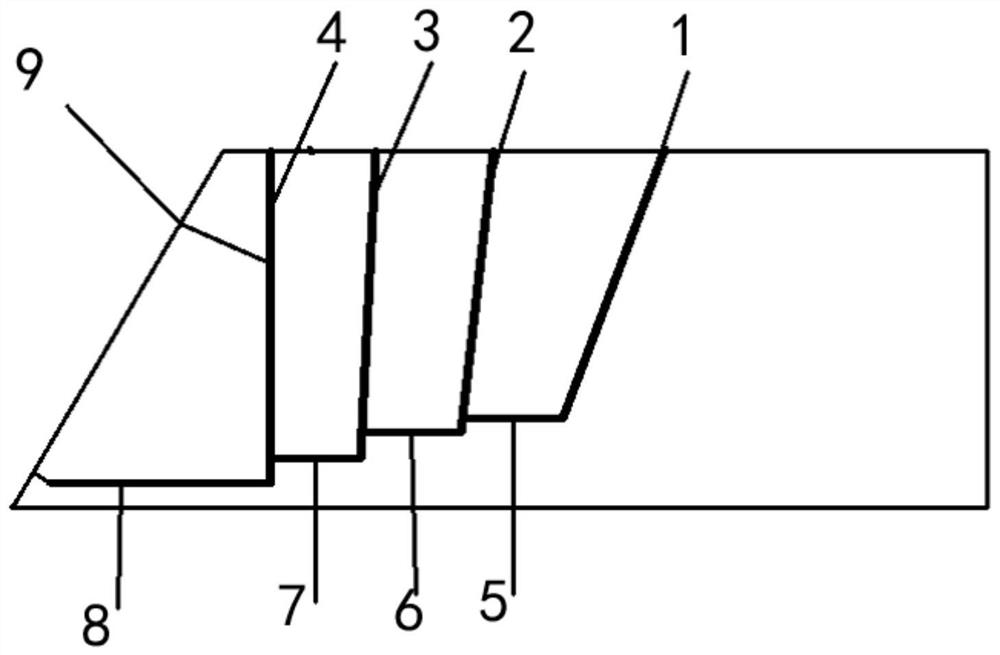
A smooth blasting and interface technology, applied in the field of blasting, can solve the problems of poor smooth blasting molding effect, increase rock wall stability, reduce over-under-excavation and support workload, etc.

Active Publication Date: 2020-10-16
内蒙古蒙西矿业有限公司
View PDF4 Cites 0 Cited by
  • Summary
  • Abstract
  • Description
  • Claims
  • Application Information

AI Technical Summary

Problems solved by technology

[0002] Smooth surface blasting is to control the range and direction of the blasting, so that the rock wall surface after blasting is smooth and flat to prevent rock cracking, reduce over-under-excavation and supporting workload, increase the stability of the rock wall, and reduce the damage caused by blasting to the retained rock mass. Furthermore, it is a technology to control the excavation profile of rock mass. In smooth blasting, the interval, depth, angle, diameter and minimum resistance line of blasting holes, and the filling amount of blasting drugs will all affect the effect of smooth blasting. In the current technology, There is no preparation method to determine these parameters, making smooth blast molding less effective

Method used


Image

  • Smooth blasting from stope to interface slope
  • Smooth blasting from stope to interface slope
  • Smooth blasting from stope to interface slope

Examples


Embodiment Construction

[0072] The above and other technical features and advantages of the present invention will be described in more detail below in conjunction with the accompanying drawings.

[0073] Preferred embodiments of the present invention are described below with reference to the accompanying drawings. Those skilled in the art should understand that these embodiments are only used to explain the technical principles of the present invention, and are not intended to limit the protection scope of the present invention.

[0074] It should be noted that, in the description of the present invention, terms such as "upper", "lower", "left", "right", "inner", "outer" and other indicated directions or positional relationships are based on the terms shown in the accompanying drawings. The direction or positional relationship shown is only for convenience of description, and does not indicate or imply that the device or element must have a specific orientation, be constructed and operated in a spec...


PUM


Abstract

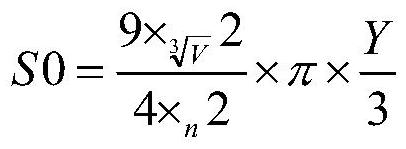
The invention relates to smooth blasting from a stope to an interface slope. The smooth blasting comprises steps as follows: an experiment stage of a blasting explosive: before blasting, the quantityof the used blasting explosive is subjected to experimental blasting; a setting stage of blasting holes: interval, depth, void and angle of the blasting holes are set, and the minimum burden is set; afilling stage of the blasting explosive: the blasting holes are filled with the explosive, and the filling quantity is determined; and a detonating stage: the filled blasting explosive is detonated according to the sequence. The experimental blasting is carried out according to actual conditions, the control blasting area SO is defined, through combination of the data with actual stratum hardness, the interval, angle, depth, filled explosive quantity and minimum burden of each blasting hole in each layout layer are designed, therefore, accuracy of each parameter of the smooth blasting is improved, and the final forming effect of the smooth blasting is improved.

Description

technical field [0001] The field of the present invention is the field of blasting, specifically the smooth surface blasting from the stope to the interface slope. Background technique [0002] Smooth surface blasting is to control the range and direction of the blasting, so that the rock wall surface after blasting is smooth and flat to prevent rock cracking, reduce over-under-excavation and support workload, increase the stability of the rock wall, and reduce the destructive effect of blasting on the retained rock mass. Furthermore, it is a technology to control the excavation profile of rock mass. In smooth blasting, the interval, depth, angle, diameter and minimum resistance line of blasting holes, and the filling amount of blasting drugs will all affect the effect of smooth blasting. In the current technology, There is no preparation method to determine these parameters, making smooth blast molding less effective. Contents of the invention [0003] The purpose of the...

Claims


Application Information

Patent Timeline
IPC IPC(8): F42D1/00F42D3/04
CPCF42D1/00F42D3/04Y02A10/23
Inventor 王飞朋王定川李世明张志祥蒋志卫王鹏寇留重
Owner 内蒙古蒙西矿业有限公司
Learn More