Eureka AIR delivers breakthrough ideas for toughest innovation challenges, trusted by R&D personnel around the world.

Dielectric loss live-line testing device for wireless sensing capacitive equipment

A technology for dielectric loss and electrification testing, which is applied to measuring devices, dielectric performance measurement, and electrical variable measurement. It can solve problems such as difficulties in regular calibration of memory test systems, hidden dangers of circuit breaks, and poor reliability.

Pending Publication Date: 2020-10-16
STATE GRID CORP OF CHINA +1
View PDF0 Cites 0 Cited by
  • Summary
  • Abstract
  • Description
  • Claims
  • Application Information

AI Technical Summary

Problems solved by technology

[0007] The purpose of the present invention is to provide a wireless sensor capacitive equipment dielectric loss electrification test device for the hidden danger of open circuit of the entire last screen grounding circuit of the junction box type device and the problem of poor reliability of the active sensor type device and the difficulty of regular calibration of the memory test system

Method used


Image

  • Dielectric loss live-line testing device for wireless sensing capacitive equipment
  • Dielectric loss live-line testing device for wireless sensing capacitive equipment
  • Dielectric loss live-line testing device for wireless sensing capacitive equipment

Examples


Embodiment 1

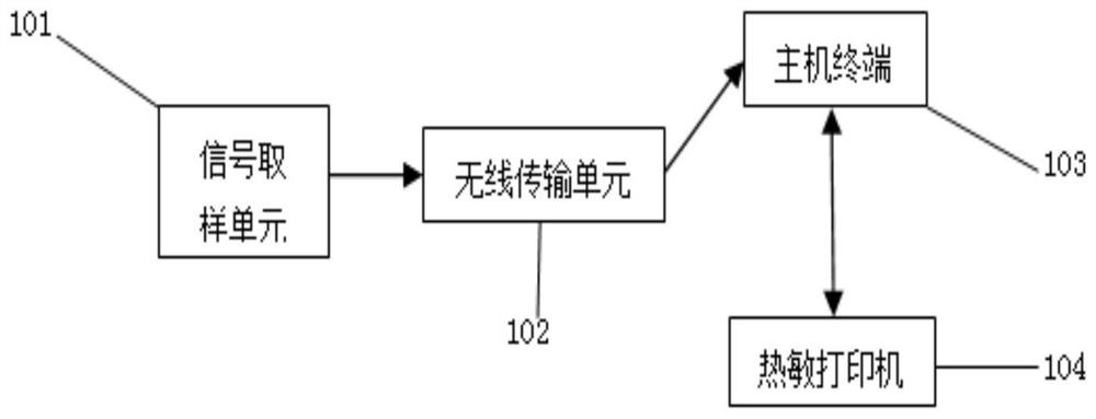
[0048] Such as figure 1 , the present embodiment is a wireless sensor capacitive equipment dielectric loss charging test device, including: a signal sampling unit 101, a wireless transmission unit 102, a host terminal 103, a thermal printer 104. The signal sampling unit 101 and the wireless transmission unit 102 are connected by wired communication, and the wireless transmission unit 102 and the host terminal 103 are both connected by wireless communication; the thermal printer 104 communicates with the host terminal 103 through a wireless Bluetooth connection.

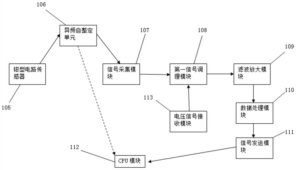
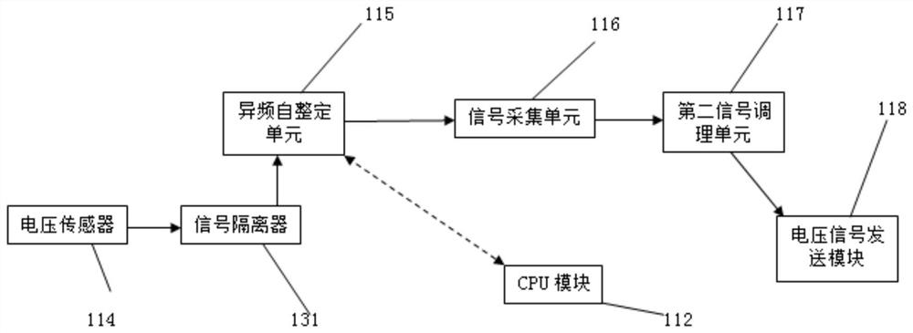
[0049] Such as figure 2 and image 3 , The signal sampling unit 101 is divided into two component systems: a current signal sampling unit and a voltage signal sampling unit. The current signal sampling unit includes a clamp-type current sensor 105, a different frequency self-tuning unit 106, a signal acquisition module 107, a first signal conditioning module 108, a filter amplification module 109, a data processin...


PUM


Abstract

The invention relates to the technical field of self-insulation state detection of high-voltage capacitive equipment in a power grid system. Aiming at the problem exposed by an existing test instrument that the whole end screen grounding circuit of the junction box type device is broken and an active sensor type device is poor in reliability and a memory test system is difficult to check regularly, the invention discloses a dielectric loss live-line testing device for wireless sensing capacitive equipment. The device comprises a signal sampling unit 101, a host terminal 103, a wireless transmission unit 102 and a thermal printer 104. The output end of the signal sampling unit 101 is connected with the input end of the wireless transmission unit 102 in a wired communication mode. The outputend of the wireless transmission unit 102 is connected with the host terminal 103 in a wireless communication manner. The thermal printer 104 is connected with the host terminal 103 in a Bluetooth communication manner. The signal sampling unit comprises a current signal sampling unit and a voltage signal sampling unit.

Description

technical field [0001] The invention relates to the technical field of self-insulation state detection of high-voltage capacitive equipment in a power grid system, and mainly aims at conducting live tests on the insulation state of capacitive equipment in high-voltage system operation. Background technique [0002] Once the high-voltage electrical equipment running in the power grid has insulation defects caused by factors such as poor manufacturing, aging, and external force damage, the high-voltage equipment and the power grid cannot operate normally. In order to prevent such safety accidents, the current traditional method is to regularly cut off the power to conduct preventive tests and maintenance after the equipment is put into operation, so as to detect the insulation defects inside the equipment in time. However, the test conditions of the power failure preventive test are quite different from the operating state, so it is not easy to correctly diagnose the insulatio...

Claims


Application Information

Patent Timeline
Patent Type & Authority Applications(China)
IPC IPC(8): G01R27/26
CPCG01R27/2694
Inventor 石碧薇苏轶超郭宁辉韩海军吴思佳李学伟郭霞白杨赞姚荃李延龙王庆涛韩楠杨新兴李力郭鑫黄建王彦红焦文静
Owner STATE GRID CORP OF CHINA
Why Eureka
Eureka Blog
Learn More