
Integral Mechanism of Retaining Wall and Its Laminating Technology

A retaining wall and encapsulation technology, which is applied in the manufacture of electrical components, inductors/transformers/magnets, circuits, etc., can solve the problem of high equipment production costs, retaining wall encapsulation and insulating tape encapsulation, high labor costs for enterprises, and low work efficiency And other issues

Active Publication Date: 2021-10-08
苏州创易技研股份有限公司
View PDF5 Cites 0 Cited by
  • Summary
  • Abstract
  • Description
  • Claims
  • Application Information

AI Technical Summary

Problems solved by technology

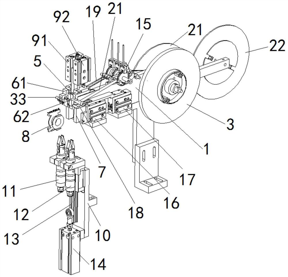
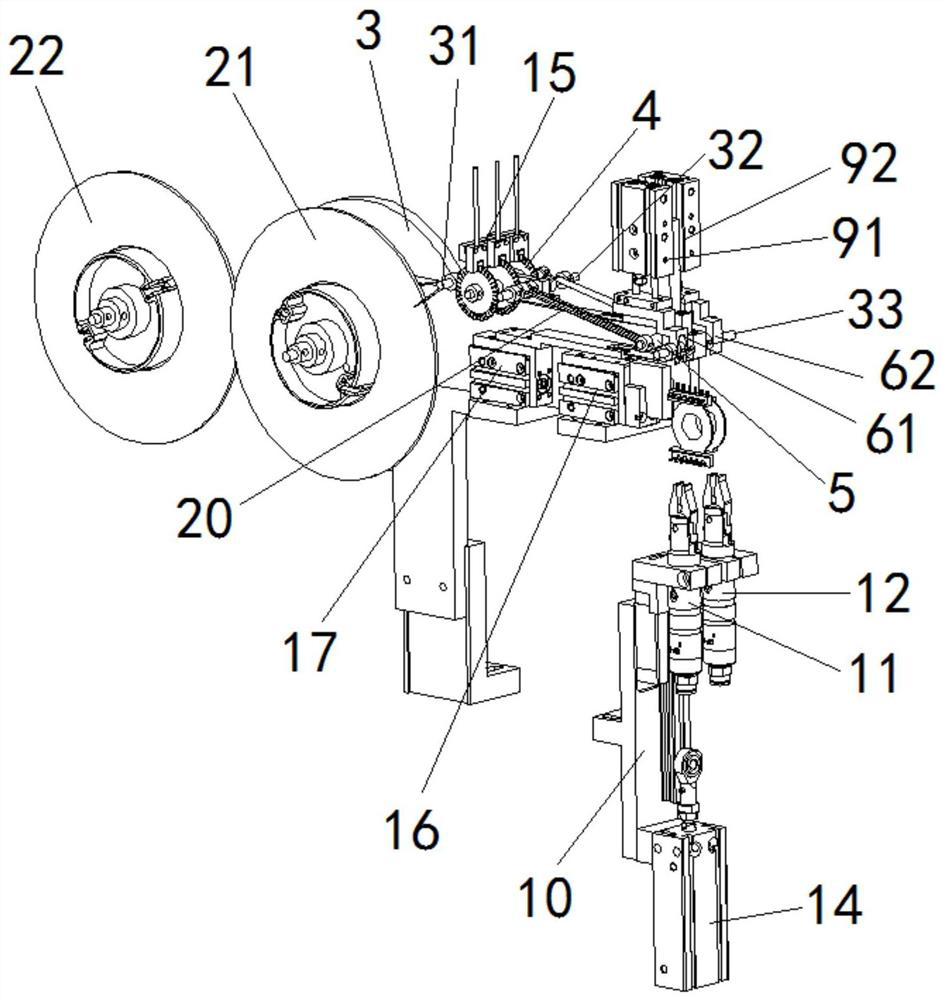
[0003] The technical problem to be solved by the present invention is to provide a retaining wall glue-wrapped integrated mechanism and its glue-covering process. Transmission, insulation tape transmission, more than two kinds of wall tape lagging and insulating tape lagging and other series of operations, and has the advantages of high lagging efficiency, high lagging precision, good lagging effect, simple structure and convenient use , which can not only wrap two kinds of retaining wall tapes on the skeleton on one device, but also realize the insulating tape wrapping on the skeleton, which not only effectively solves the traditional manual method of wrapping the skeleton with retaining wall tape Glue and insulating tape encapsulation lead to the problems of low work efficiency, poor encapsulation effect, high labor intensity of workers and high labor cost of enterprises. It also solves the current winding machine with semi-automatic retaining wall encapsulation function even if the structure Complex, bulky and high equipment manufacturing costs still cannot realize the problem that more than two kinds of retaining wall lagging and insulating tape lagging can be performed on the skeleton on one device

Method used


Image

  • Integral Mechanism of Retaining Wall and Its Laminating Technology
  • Integral Mechanism of Retaining Wall and Its Laminating Technology

Examples


Embodiment Construction

[0019] In order to facilitate the understanding of the present invention, the present invention will be described more fully below with reference to the associated drawings. Preferred embodiments of the invention are shown in the accompanying drawings. However, the present invention can be embodied in many different forms and is not limited to the embodiments described herein. On the contrary, the purpose of providing these embodiments is to make the disclosure of the present invention more thorough and comprehensive.

[0020] Unless otherwise defined, all technical and scientific terms used herein have the same meaning as commonly understood by one of ordinary skill in the technical field of the invention. The terminology used herein in the description of the present invention is only for the purpose of describing specific embodiments, and is not intended to limit the present invention.

[0021] In this example, refer to Figure 1 to Figure 2As shown in the figure, the ret...


PUM


Abstract

The retaining wall glue-covering integrated mechanism of the present invention includes two retaining wall tape reels, an insulating tape reel, several tape guide shafts, a tape drive wheel assembly, a tape guide wheel, two pressing fixtures, adhesive seats, two Glue pressing cylinder, two tape clamping cylinders, transfer cylinder, tape sensor, glue cylinder, tape cutting cylinder and tape cutting blade, etc. The invention can complete a series of operations such as wire winding, transmission of more than two types of retaining wall tapes, transmission of insulating tapes, encapsulation of two or more types of retaining wall tapes and insulation tape encapsulation on one piece of equipment. With the advantages of high glue efficiency, good glue effect, simple structure and convenient use, it not only solves the problems of low work efficiency, poor glue effect, high labor intensity of workers and high labor cost of enterprises in traditional manual glue wrap, but also It solves the problem that the current winding machine with semi-automatic retaining wall wrapping function cannot perform more than two kinds of retaining wall wrapping and insulating tape wrapping on the skeleton on one device.

Description

technical field [0001] The invention relates to an integrated mechanism of a retaining wall with rubber covering and a rubber covering process thereof. Background technique [0002] Traditionally, the wall tape wrapping of the coil bobbin is manually operated, and the manual tape wrapping of the frame has the disadvantages of low work efficiency, poor wrapping effect, high labor intensity of workers and high labor cost of the enterprise. Later, some winding machines on the market had a semi-automatic retaining wall covering mechanism, but due to unreasonable design, it had the disadvantages of complex structure, large volume, high equipment manufacturing cost, troublesome maintenance and high maintenance cost, and it could not be realized. On one piece of equipment, more than two types of retaining wall coatings can be performed on the skeleton, insulation tape can be applied to the skeleton, and the skeleton can be wound. As a result, its functional and structural design co...

Claims


Application Information

Patent Timeline
Patent Type & Authority Patents(China)
IPC IPC(8): H01F41/00
CPCH01F41/00
Inventor 倪锦程陈刚
Owner 苏州创易技研股份有限公司
Learn More