Eureka AIR delivers breakthrough ideas for toughest innovation challenges, trusted by R&D personnel around the world.

Fastening device for milling machine cutter

A fastening device and tool technology, applied in milling cutters, milling machine equipment, manufacturing tools, etc., can solve problems such as decreased physical strength, high risk factor, and safety accidents.

Inactive Publication Date: 2020-10-20
刘光旭
View PDF0 Cites 2 Cited by
  • Summary
  • Abstract
  • Description
  • Claims
  • Application Information

AI Technical Summary

Problems solved by technology

[0003] The current vertical ordinary milling machine generally only uses a screw to fix the tool, and when installing, the general staff always climbs to the operating platform, and then installs the tool on the working head with one hand Then the other hand installs the tool by twisting the upper screw, so that when the staff works for a long time, people will be fatigued, resulting in a decrease in physical strength, which will cause a safety accident, and when the tool is replaced , after the milling machine runs for a period of time, it will cause the milling cutter to loosen, and it is necessary to stop the milling machine to tighten the milling cutter, which has a high risk factor and delays production

Method used


Image

  • Fastening device for milling machine cutter
  • Fastening device for milling machine cutter
  • Fastening device for milling machine cutter

Examples


Embodiment Construction

[0029] The present invention is described in further detail now in conjunction with accompanying drawing. These drawings are all simplified schematic diagrams, which only illustrate the basic structure of the present invention in a schematic manner, so they only show the configurations related to the present invention.

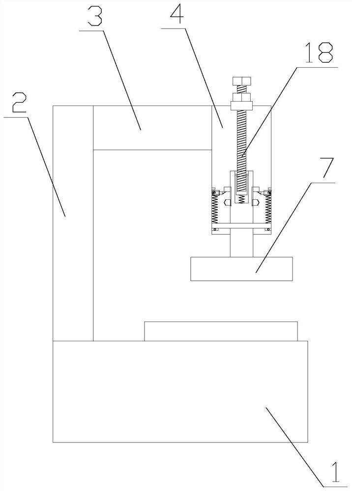
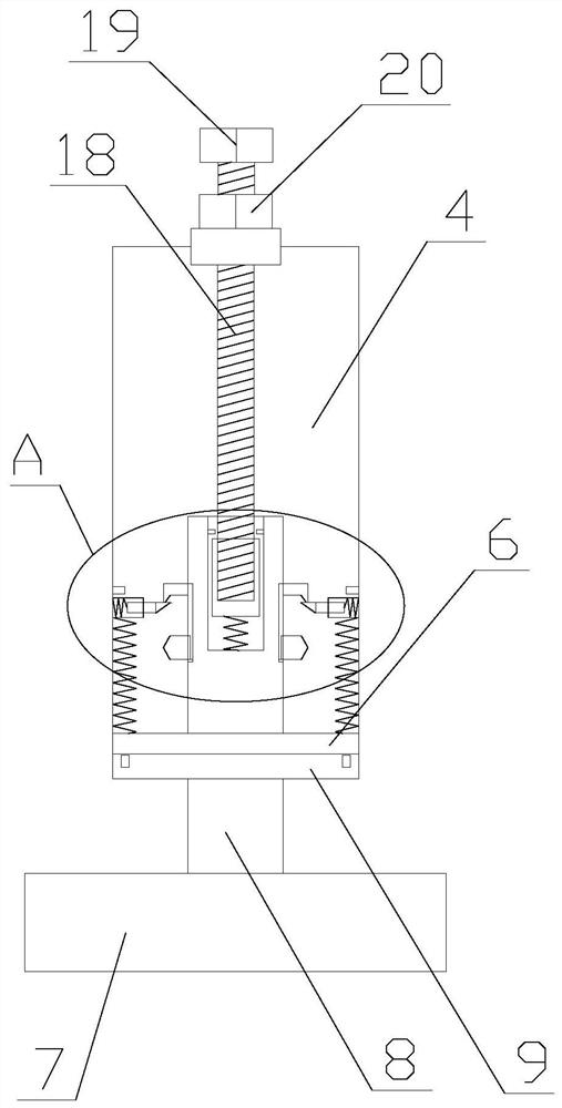
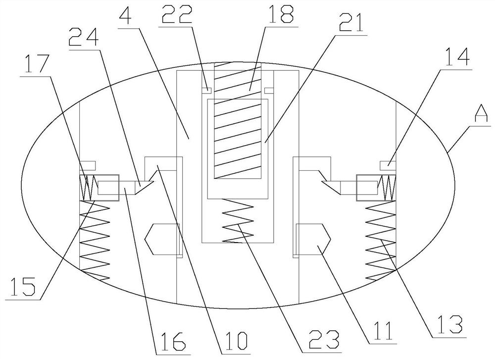
[0030] like Figure 1-5 As shown, a fastening device for a milling machine tool includes a base 1, a column 2, a beam 3, a fixed block 4, a positioning plate 5, a tool, a supporting mechanism and a connecting mechanism, the base 1 is horizontally arranged, and the beam 3 is set above the base 1, the column 2 is vertically set on the base 1, the fixed block 4 is vertically set on one side of the column 2, the beam is located between the fixed block 4 and the column 2, the fixed block 4 The block 4 is connected with the column 2 through the beam 3, the fixed block 4 is cylindrical, and the fixed block 4 is hollowly arranged, the cutter, the support mechanism an...


PUM


Abstract

The invention relates to a fastening device for a milling machine tool. The device comprises a base, a stand column, a cross beam, a fixing block, a positioning plate, a cutter, a supporting mechanismand a connecting mechanism. The cutter comprises a cutter head, a cutter handle, a connecting plate, a positioning block and a moving block; the supporting mechanism comprises a first spring, a firstlimiting block, a piston cylinder, a supporting rod and a second spring; and the connecting mechanism comprises a screw rod and a first screw cap. According to the fastening device for the milling machine cutter, when a worker installs the cutter, the cutter can be fastened through the supporting mechanism, so that a worker can fix the screw cap by two hands, the condition that hands or feet areinjured as one hand cannot hold the cutter due to the too heavy cutter can be avoided, and further the safety during installation is improved. Primary fixing of the cutter is achieved through fixing of a bolt and a positioning strip, the positioning strip can further limit the cutter, the screw rod is more firmly connected with the cutter handle through cooperation of the screw rod and a sleeve, secondary fixing of the cutter is achieved, and the use practicability is improved.

Description

technical field [0001] In particular, the invention relates to a fastening device for milling machine tools. Background technique [0002] A milling machine is a machine tool with a wide range of uses. It can process planes (horizontal planes, vertical planes), grooves (key slots, T-shaped slots, dovetail slots, etc.), toothed parts (gears, spline shafts, sprockets), Spiral surface (thread, spiral groove) and various curved surfaces. In addition, it can also be used to process and cut off the surface and inner hole of the rotary body. When the milling machine is working, the workpiece is installed on the workbench or on the accessories such as the dividing head. , the rotation of the milling cutter is the main movement, supplemented by the feed movement of the table or the milling head, the workpiece can obtain the required processing surface, because it is multi-blade intermittent cutting, so the productivity of the milling machine is high. Simply put, the milling machine ...

Claims


Application Information

Patent Timeline
Patent Type & Authority Applications(China)
IPC IPC(8): B23C5/26
CPCB23C5/26
Inventor 刘光旭
Owner 刘光旭
Why Eureka
Eureka Blog
Learn More