
Turning and grinding integrated machine with locating structure and for numerical control machining

A positioning structure and mechanical processing technology, applied in positioning devices, manufacturing tools, metal processing, etc., can solve the problems of inconvenient debris collection, cumbersome structure, and inconvenient rotation

Inactive Publication Date: 2020-10-20
叶彭婷
View PDF0 Cites 2 Cited by
  • Summary
  • Abstract
  • Description
  • Claims
  • Application Information

AI Technical Summary

Problems solved by technology

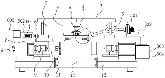
[0004] The object of the present invention is to provide a turning and grinding integrated machine with a positioning structure for numerical control machining, so as to solve the problem that the turning and grinding integrated machine proposed in the above background technology has relatively limited positioning function during use, and the structure is cumbersome, which is inconvenient for users to operate. , and it is inconvenient to rotate during the positioning process of the article, and it is inconvenient to perform multi-angle grinding and processing operations, which brings inconvenience to the user, and it is inconvenient for the user to collect the debris after grinding during use, and it is inconvenient for the user to The problem of dredging the temperature of the motor when it is working

Method used


Image

  • Turning and grinding integrated machine with locating structure and for numerical control machining
  • Turning and grinding integrated machine with locating structure and for numerical control machining
  • Turning and grinding integrated machine with locating structure and for numerical control machining

Examples


Embodiment Construction

[0026] The following will clearly and completely describe the technical solutions in the embodiments of the present invention with reference to the accompanying drawings in the embodiments of the present invention. Obviously, the described embodiments are only some, not all, embodiments of the present invention. Based on the embodiments of the present invention, all other embodiments obtained by persons of ordinary skill in the art without making creative efforts belong to the protection scope of the present invention.

[0027] In the description of the present invention, unless otherwise stated, the meaning of "plurality" is two or more; the terms "upper", "lower", "left", "right", "inner", "outer" , "front end", "rear end", "head", "tail", etc. indicate the orientation or positional relationship based on the orientation or positional relationship shown in the drawings, and are only for the convenience of describing the present invention and simplifying the description, rather...


PUM


Abstract

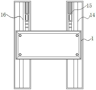
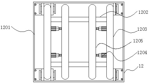
The invention discloses a turning and grinding integrated machine with a locating structure and for numerical control machining, and relates to the technical field of turning and grinding integrated machines. The turning and grinding integrated machine comprises a top plate and a base. A top cavity is arranged at the bottom of the top plate, and an adjusting device is mounted in the top cavity. Through the arrangement of a fan, when a grinding wheel is driven through the combined action of a second motor and a connecting shaft to rotate to machine objects needing to be machined, scraps duringmachining can be absorbed through the fan, and the problems that many scraps are generated in the object machining process, and inconvenience is brought to object machining are avoided; and meanwhile,the fan is connected with a dust collection frame through a windblown dust pipe, finally absorbed dust can fall into a drawing groove in the dust collection frame, the drawing groove can be moved outfrom the interior of the dust collection frame in the long-time use process, users can treat dust in the drawing groove conveniently in a unified manner, the structure is simple, and the machine is convenient for users to use.

Description

technical field [0001] The invention relates to the technical field of a turning and grinding integrated machine, in particular to a turning and grinding integrated machine with a positioning structure for numerical control machining. Background technique [0002] Numerical control technology is the base for the manufacturing industry to realize automation, flexibility and integrated production. It is the core of modern manufacturing technology and an essential means to improve the product quality and labor productivity of the manufacturing industry. The grinding device is used, and the performance of the grinding device is becoming more and more perfect with the continuous development and progress of the times. [0003] The turning and grinding all-in-one machines on the market have limited positioning functions during use, and the structure is cumbersome, which is inconvenient for users to operate, and it is inconvenient to rotate during the positioning process of objects,...

Claims


Application Information

Patent Timeline
IPC IPC(8): B23Q3/08B23Q7/02B23Q11/00B23Q11/12B23Q41/06B23Q41/08
CPCB23Q3/082B23Q7/02B23Q11/0046B23Q11/127B23Q41/06B23Q41/08
Inventor 陈钰
Owner 叶彭婷
Learn More