
Manufacturing method of composite core shaft for lightweight spherical hinge and lightweight spherical hinge

A technology of composite mandrel and manufacturing method, which is applied to shafts, pivots, shafts and bearings, etc., can solve the problems of large cutting amount and low material utilization rate.

Active Publication Date: 2020-10-20
ZHUZHOU TIMES NEW MATERIALS TECH
View PDF8 Cites 1 Cited by
  • Summary
  • Abstract
  • Description
  • Claims
  • Application Information

AI Technical Summary

Problems solved by technology

For elastic joints produced in small batches, the metal mandrel generally uses round steel as the raw material, and the outer dimensions of the mandrel are obtained by cutting. The cutting amount is large during the processing, and the material utilization rate is not high.

Method used


Image

  • Manufacturing method of composite core shaft for lightweight spherical hinge and lightweight spherical hinge
  • Manufacturing method of composite core shaft for lightweight spherical hinge and lightweight spherical hinge
  • Manufacturing method of composite core shaft for lightweight spherical hinge and lightweight spherical hinge

Examples


Embodiment 1

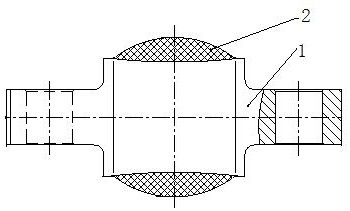
[0045]A method for manufacturing a composite mandrel for a lightweight spherical hinge. The composite mandrel for a lightweight spherical hinge includes a metal mandrel 1 and a winding section 2 solidified on the middle section of the metal mandrel 1. The outer wall of the winding section 2 is from two ends to A convex spherical surface with gradually increasing middle diameter, characterized in that the manufacturing steps are as follows:

[0046] S1: Design the weight ratio of the metal mandrel 1 and the winding section 2 according to the lightweight requirements of the lightweight spherical hinge, and design the size of the metal mandrel 1 and the winding section 2 according to the weight and size requirements of the lightweight spherical hinge;

[0047] S2: Manufacture the metal mandrel 1, and process a positioning structure for axially positioning the winding section 2 in the middle section of the metal mandrel 1;

[0048] S3: Winding the resin-impregnated glass fiber to ...

Embodiment 2

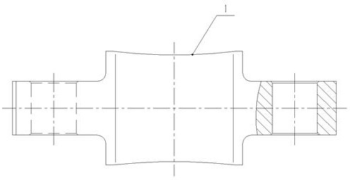
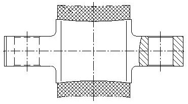
[0059] The difference from Embodiment 1 is that "processing a positioning structure for axially positioning the winding section 2 in the middle section of the metal mandrel 1" in step S2 refers to dividing the middle section of the metal mandrel 1 into The straight section 11 at the end, the raised section 12 between the two straight sections 11 and the positioning section 13 between the straight section 11 and the raised section 12, the straight section 11 is straight, and the raised section 12 is From both ends to the middle, the diameter gradually increases and the surface is smooth. The positioning section 13 is an inner concave ring groove with a diameter smaller than the straight section 11 and the convex section 12. The winding section 2 is positioned axially by the positioning section 12. A concave annular groove-shaped positioning section 13 is processed in the middle section of the metal mandrel, and the winding section 2 is axially positioned through the positioning ...


PUM


Abstract

The invention discloses a manufacturing method of a composite core shaft for a lightweight spherical hinge. The composite core shaft for the lightweight spherical hinge comprises a metal core shaft and a winding segment fixed to the middle segment of the metal core shaft, and the outer wall of the winding segment is an outward convex spherical face with the diameters gradually increased from the two ends to the middle. The method comprises the manufacturing steps that according to the lightweight requirement of the lightweight spherical hinge, the weight proportion of the metal core shaft andthe winding segment is designed, and the sizes of the metal core shaft and the winding segment are designed out according to the weight and size requirements of the lightweight spherical hinge; the metal core shaft is manufactured, and a locating structure used for carrying out axial locating on the winding segment is machined in the middle segment of the metal core shaft; and resin infiltrated glass fibers are wound to the middle segment of the metal core shaft through a winding process, after winding, resin gelling and curing forming are carried out, and then the winding segment meeting thesize design requirement is formed through machining. The mass of the core shaft is relieved, axial locating of the winding segment and the metal core shaft is guaranteed, and the use performance of the spherical hinge is not influenced while lightweight operation is achieved. The invention further provides the lightweight spherical hinge.

Description

technical field [0001] The invention relates to a manufacturing method of a composite mandrel for a lightweight spherical hinge and a lightweight spherical hinge, and belongs to the technical field of spherical hinge manufacture. Background technique [0002] Appendix A of TB / T2843-2015 "General Technical Conditions for Rubber Elastic Components Used in Locomotives" gives examples and schematic diagrams of common rubber elastic elements. The role of flexible connection and buffer vibration shock. In order to increase the radial stiffness and axial stiffness of the elastic joints and reduce the deflection stiffness, the shape of the metal mandrel bonded with rubber is generally designed to be spherical or approximately spherical. This type of elastic joint is also called a "spherical joint". For the elastic nodes of this type of spherical mandrel, the weight of the metal mandrel is relatively heavy. For elastic joints produced in small batches, the metal mandrel generally u...

Claims


Application Information

Patent Timeline
IPC IPC(8): B29C70/34B29C70/74B29C70/54F16C11/06
CPCB29C70/34B29C70/74B29C70/54F16C11/0685F16C2322/00
Inventor 曾繁盛林立钿王振
Owner ZHUZHOU TIMES NEW MATERIALS TECH
Learn More