Vehicle-mounted unmanned aerial vehicle storage control platform

A control platform and machine storage technology, applied in the field of vehicle-mounted drone storage control platform, can solve the problems of drone crash, impact on landing speed, high risk, etc.

Inactive Publication Date: 2020-10-20
JILIN TEACHERS INST OF ENG & TECH
View PDF0 Cites 0 Cited by
  • Summary
  • Abstract
  • Description
  • Claims
  • Application Information

AI Technical Summary

Problems solved by technology

[0002] The take-off and landing phase of the multi-rotor UAV is usually required to be carried out on a relatively flat field. If the surface of the landing area is inclined, potholes or large stones, etc., it is difficult for the sensor on the UAV to accurately judge the distance between the UAV tripod and the ground. The landing in this state will undoubtedly increase the possibility of UAV crashing, especially when it affects the speed control when landing, causing the UAV to stall or land at high speed and crash; UAV take-off and landing require a sufficient safety area at the same time, especially In places with dense crowds or traffic, such as stations or squares, if there is no suitable landing place, the risk of landing due to many uncontrollable factors is greater
In addition, when the multi-rotor drone lands, it needs to adjust the position slowly, and then finally land; the drone is easy to jump after landing, and it is not controlled by the remote control, which is more dangerous at this time

Method used


Image

  • Vehicle-mounted unmanned aerial vehicle storage control platform
  • Vehicle-mounted unmanned aerial vehicle storage control platform
  • Vehicle-mounted unmanned aerial vehicle storage control platform

Examples


Embodiment Construction

[0028] The present invention will be further described in detail below in conjunction with the accompanying drawings.

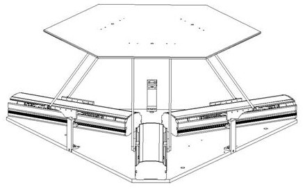
[0029] Such as figure 1 As shown, a schematic diagram of a vehicle-mounted UAV storage control platform assembly provided in this embodiment.

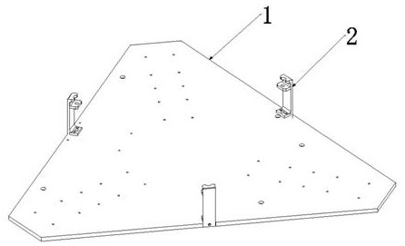
[0030] Such as figure 2 Shown is the base system, including base 1, stopper 2.

[0031] The base 1 is in the shape of a unequal hexagon, which can be divided into short sides and long sides; the length of the three short sides is equal to the width and length of the housing A3 in the drive system, and there is a supply limit at the midpoint of the three long sides. The groove where the limiter 2 is installed; the lower end of the limiter 2 has a lug that matches the groove of the base 1.

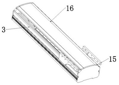
[0032] Such as image 3 The drive system is shown, which includes: shell A3, geared motor holder 4, planetary geared motor 5, coupling A6, trapezoidal screw 7, flange nut 8, smooth bracket 9, linear guide rail 10, square slider...


PUM


Abstract

The invention relates to the technical field of unmanned aerial vehicle flight assistance equipment, and discloses a vehicle-mounted unmanned aerial vehicle storage control platform. The vehicle-mounted unmanned aerial vehicle storage control platform comprises a base system, driving systems, a connecting rod assembly and a regular hexagonal platform, wherein the base system comprises a base and alimiter; the base is fixedly connected with the driving systems; the connecting rod assembly is fixedly connected with the driving systems; and the regular hexagonal platform is fixedly connected with the connecting rod assembly. According to the invention, vibration signals are converted into electric signals through sensors, the electric signals are amplified through an electronic circuit and then transmitted to a motor controller, stepping motors in the three sets of driving systems operate at the same time to control lifting of the regular hexagonal platform, and the influence of jolt generated by special road conditions on lifting or standing of the flight vehicle in the vehicle advancing process is reduced; and the platform is installed at a designated position and can provide an unmanned aerial vehicle emergency take-off and landing point, the unmanned aerial vehicle returns to the platform and is stored after completing tasks, and functions are complete.

Description

technical field [0001] The invention relates to the technical field of UAV flight auxiliary equipment, in particular to a vehicle-mounted UAV storage control platform. Background technique [0002] The take-off and landing phase of the multi-rotor UAV is usually required to be carried out on a relatively flat field. If the surface of the landing area is inclined, potholes or large stones, etc., it is difficult for the sensor on the UAV to accurately judge the distance between the UAV tripod and the ground. The landing in this state will undoubtedly increase the possibility of UAV crashing, especially when it affects the speed control when landing, causing the UAV to stall or land at high speed and crash; UAV take-off and landing require a sufficient safety area at the same time, especially In places with dense crowds or traffic, such as stations or squares, if there is no suitable landing site, the risk of landing due to many uncontrollable factors is greater. In addition, ...

Claims


Application Information

Patent Timeline
IPC IPC(8): B64F1/00
CPCB64F1/00B64U10/10B64U80/86
Inventor 李明月管荣强于静邵芳吴悦罗红宇刘子超
Owner JILIN TEACHERS INST OF ENG & TECH
Why Eureka
Try Eureka