a ball valve

A ball valve and valve body technology, applied in valve details, valve device, valve operation/release device, etc., can solve the problems of shortening the service life of the ball valve, economic loss, affecting production efficiency, etc., to improve the service life and save replacement. Time, long service life effect

Active Publication Date: 2021-09-07
OUQIU VALVE CO LTD
View PDF0 Cites 0 Cited by
  • Summary
  • Abstract
  • Description
  • Claims
  • Application Information

AI Technical Summary

Problems solved by technology

[0003] (1) In order to ensure that no internal leakage occurs in the existing ball valve, the ball, that is, the closing part, must be pressed tightly on the valve seat during installation. The torque is large when opening and closing. Friction, serious wear, easy to cause leakage, reduce the working reliability of the ball valve, and shorten the service life of the ball valve; however, the sealing surface of the existing ball valve ball is fixed, when the sealing surface of the valve ball is damaged, the entire pipeline needs to be stopped Or equipment, remove the entire ball valve to repair or replace the valve ball, affecting production efficiency, and many working conditions do not allow the equipment to shut down, once shut down will cause major economic losses;
[0004] (2) The ball valve of the prior art cannot achieve throttling and flow control. In order to adjust the flow in the pipeline, it is also necessary to add a flow regulating valve in the pipeline, which increases the configuration cost of the pipeline

Method used


Image

  • a ball valve
  • a ball valve
  • a ball valve

Examples


Embodiment Construction

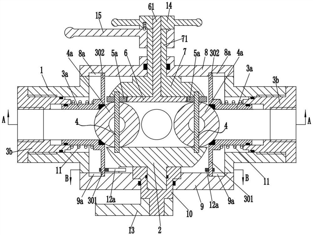
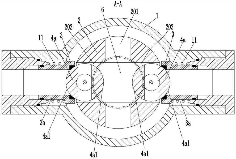
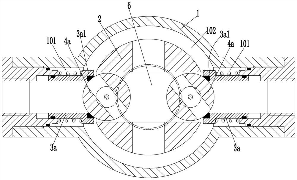
[0030] see Figure 1-10 As shown, a ball valve includes a valve body 1, the valve body 1 is provided with a channel 101 penetrating left and right, the valve body 1 is provided with a mounting hole 102 along the direction perpendicular to the channel 101, and the valve body 1 is An upper end cover 8 is installed on the upper end of the mounting hole 102, and a lower end cover 9 is installed on the lower end of the mounting hole 102; the lower end cover 9 is connected to the lower rotating shaft 10 along the axial direction of the mounting hole 102, and the lower end of the lower rotating shaft 10 is fixed. A second handle rod 13 is installed; the upper end of the lower shaft 10 in the mounting hole 102 is rotatably connected to the lower valve ball 2, and the lower valve ball 2 is provided with a flow hole 201; the upper end cover 8 is rotatably connected to a lower end The sleeve rod 71 extending into the installation hole 102, the lower end of the sleeve rod 71 is provided w...


PUM


Abstract

The invention discloses a ball valve, which comprises a valve body. A channel and a mounting hole are arranged in the valve body. An upper end cover is installed on the upper end of the valve body in the installation hole, and a lower end cover is installed on the lower end of the valve body; The lower rotating shaft, the upper end of the lower rotating shaft in the installation hole is rotated to connect with the lower valve ball; the upper end cover is rotated and connected with a sleeve rod, and the lower end of the sleeve rod is provided with a ball cover; both ends of the passage are fixedly installed with A screw sleeve, the valve seat cylinder is slidably connected to the inside of the screw sleeve, and a shoulder is provided on the outside of the valve seat cylinder; a spring is arranged between the screw sleeve and the shoulder; a first transmission component is arranged in the installation hole ; The lower valve ball is provided with a mounting groove, and each mounting groove is rotatably connected with a shaft; each shaft is fixedly installed with a ball core; the sleeve rod is rotatably connected with an adjustment rod, and the lower valve There is a second transmission assembly inside the ball; the ball valve not only has a simple structure, but also can replace the sealing surface of the ball core on-line without stopping the machine.

Description

technical field [0001] The invention belongs to the technical field of pipeline valves, in particular to a ball valve. Background technique [0002] Pipelines are usually used to transport media in industrial or civil infrastructure, where the pipeline is regulated due to changes in pressure or temperature. In order to adjust the flow, an adjustment mechanism, especially a ball valve, is used in the pipeline to ensure the best work. conditions and the safety of the environment. Ball valves usually use a sphere with a circular passage as the opening and closing element, and the sphere realizes the opening and closing action with the rotation of the valve body. The opening and closing part of the ball valve is a ball with a through hole, which rotates around the axis perpendicular to the channel, so as to achieve the purpose of opening and closing the channel. A traditional ball valve is usually a sphere with a through hole installed on the valve seat, and the opening and cl...

Claims


Application Information

Patent Timeline
Patent Type & Authority Patents(China)
IPC IPC(8): F16K5/06F16K5/10F16K5/20F16K31/53F16K31/60
CPCF16K5/0605F16K5/0647F16K5/10F16K5/201F16K31/535F16K31/602
Inventor 武芳李辉洪德朋
Owner OUQIU VALVE CO LTD
Why Eureka
Try Eureka