Separate fusible alloy structure security release device

A technology of fusible alloy and safety relief, which is applied to the installation device of container structure, safety valve, valve device, etc., which can solve the problem of large discharge area, failure to fully reflect the protection function of safety devices, and frequent bursting discs. Issues such as detonation

Pending Publication Date: 2020-10-20
CHINA SPECIAL EQUIP INSPECTION & RES INST +1
View PDF0 Cites 2 Cited by
  • Summary
  • Abstract
  • Description
  • Claims
  • Application Information

AI Technical Summary

Problems solved by technology

However, in actual use, it is found that the bursting disc-fusible alloy combination device can detonate smoothly only when the gas pressure in the gas cylinder and the ambient temperature exceed the design threshold at the same time. It can be well reflected that this type of safety relief device did not operate in many long-tube trailer fire accidents, which illustrates this point
In addition, there are some problems in the safety relief device of the single bursting disc device and the bursting disc-fusible alloy combination device when replacing the bursting disc: the safety relief device needs to be disassembled from the long tube trailer and then fixed on a special tooling and a special Tighten it with a torque wrench, and at the same time ensure that the bursting disc is placed vertically in the center of the holder of the safety relief device, which requires high working conditions and operating skills, otherwise the replacement quality cannot be guaranteed, resulting in the newly replaced bursting disc being placed in the center of the safety relief device holder. Frequent detonation under non-design working conditions will bring unpredictable impact on the safe operation of enterprises and social stability and harmony
For large-volume high-pressure gas cylinders, the discharge area is much larger, the fusible alloy itself is soft, and the pressure-bearing capacity is very poor. The original structure cannot be directly used at all.

Method used


Image

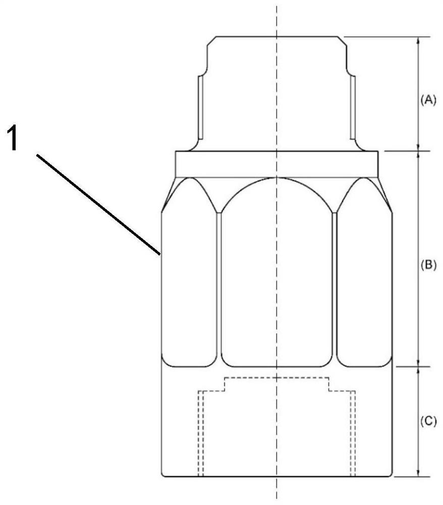
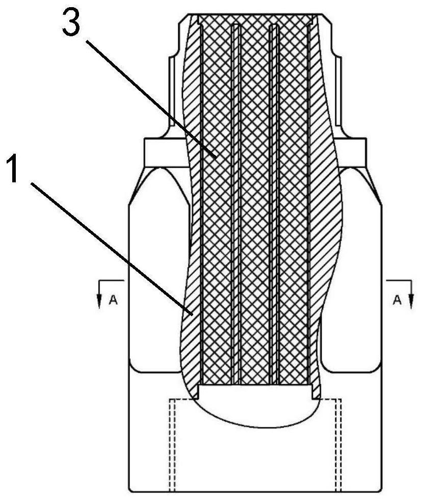
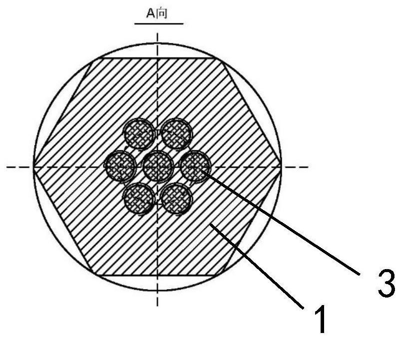
  • Separate fusible alloy structure security release device
  • Separate fusible alloy structure security release device
  • Separate fusible alloy structure security release device

Examples


Embodiment approach

[0050] Under the overall framework of the aforementioned technical solutions, the preferred embodiments of the present invention are supplemented as follows:

[0051] 1. The base material of the pressure-bearing structure 1 can be made of brass or stainless steel, which can be selected according to the compatibility of the medium in the large-volume high-pressure gas cylinder, and the mechanical properties of the material should meet the requirements of relevant regulations and standards;

[0052] 2. The fusible alloy is recommended to be selected in accordance with the fusible alloy formula in Appendix A of GB8337 "Fusible Alloy Plug Device for Gas Cylinders", the melting zone temperature (action temperature) is 102.5±5°C, that is, the Bi content is 53.9% (weight content, the same below), Sn content 25.9%, Cd content 20.2%, eutectic state; users can also choose fusible alloy materials with other melting temperatures according to working conditions and special needs; design sho...


PUM


Abstract

The invention provides a separate fusible alloy structure security release device. The separate fusible alloy structure security release device comprises a pressure bearing structure, one end of the pressure bearing structure is used for being connected with a high pressure pipeline, the other end of the pressure bearing structure is used for being connected with a blowdown pipeline, a plurality of pressure release holes are formed between two ends of the pressure bearing structure, and fusible alloys are injected into the pressure release holes. A porous structure is adopted, compared with aconventional single-hole structure, the porous structure has the advantages that the jointing area of the shaped fusible alloys with the inner surface of a hole channel can be enlarged, the shearing strength of part of the fusible alloys can be reinforced, a conventional rupture disk structure is not used, and the condition that after a gas cylinder is burnt by a fire, internal pressure of the gascylinder is insufficient to achieve operating pressure of a rupture disk and the pressure cannot be released, so that invalidation is caused, can be effectively avoided.

Description

technical field [0001] The invention relates to the field of safety explosion-proof technology for high-pressure gas cylinders, in particular to a separate fusible alloy structure safety relief device for large-volume high-pressure gas cylinders composed of long-tube trailers and tube-bundle containers, which belongs to the research on safety accessories for special equipment field. Background technique [0002] With the adjustment of the national energy policy and the social emphasis on the living environment, clean energy represented by natural gas and hydrogen has been widely used, and the demand for compressed gas transportation between different places is also increasing day by day. Due to the high initial investment and high energy consumption of the pipeline network, the small storage and transportation capacity of traditional small and medium-volume gas cylinders, and the difficulty in achieving uninterrupted large-scale gas supply, the large-volume high-pressure gas...

Claims


Application Information

Patent Timeline
Patent Type & Authority Applications(China)
IPC IPC(8): F16K17/38F16K17/40F17C13/04F17C13/12
CPCF16K17/383F16K17/403F17C13/04F17C13/12F17C2205/0317F17C2205/0332F17C2260/042
Inventor 张君鹏韩文超任吉超崔栋梁谢飞欧三立金志伟韩凤娟孙永国
Owner CHINA SPECIAL EQUIP INSPECTION & RES INST
Why Eureka
Try Eureka