
Gas electromagnetic heating device and control method

A technology of electromagnetic heating device and control method, which is applied in heating methods, air heaters, fluid heaters, etc., and can solve problems such as inaccurate temperature control, low thermal efficiency, and large volume

Pending Publication Date: 2020-10-20
HUBEI WUFENG HUASHENG TEA MACHINERY
View PDF0 Cites 0 Cited by
  • Summary
  • Abstract
  • Description
  • Claims
  • Application Information

AI Technical Summary

Problems solved by technology

The coal-fired hot blast stove heats the air when the air passes through the interlayer between the furnace and the shell, and contacts the inner wall of the interlayer and the surface of the heat sink in the interlayer to heat the air, but its volume is large and its thermal efficiency is low. The temperature is controlled by how much fuel is added. The control is not precise; the electric heating tube type hot blast stove and the electric ceramic sheet hot blast stove have high thermal efficiency, fast temperature rise, and controllable temperature. It only has the function of heating normal air, and cannot heat steam with high humidity

Method used


Image

  • Gas electromagnetic heating device and control method
  • Gas electromagnetic heating device and control method
  • Gas electromagnetic heating device and control method

Examples


Embodiment 1

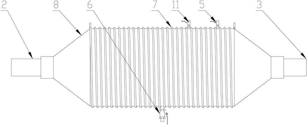
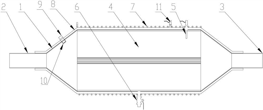
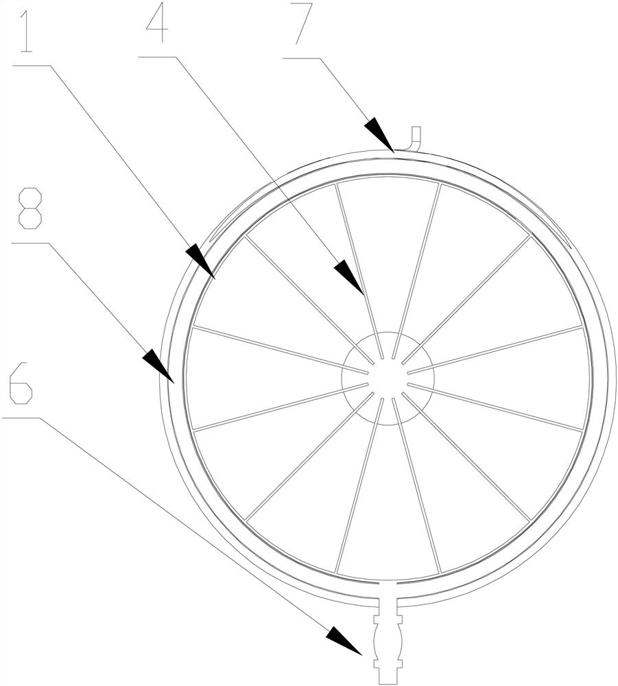
[0031] see Figure 1-5 , a gas electromagnetic heating device, which includes a cylinder 1, one end of the cylinder 1 is provided with an air inlet 2, the other end of the cylinder 1 is provided with an air outlet 3, and the inside of the cylinder 1 is provided with uniformly distributed It is a heat sink 4 that emits radiation. The outside of the cylinder 1 is wrapped with a heat-insulating insulating layer 8, and the outside of the heat-insulating insulating layer 8 is wound with a high-temperature-resistant wire 7. The high-temperature-resistant wire 7 and electromagnetic induction heating The power supply 13 is connected. The heating device can be used not only for heating dry air, for providing dry hot air, but also for heating steam with high humidity, for generating high-temperature steam, and for steam greening during tea processing. In the specific working process, the above-mentioned electromagnetic induction heating power supply 13 can provide current to the high t...

Embodiment 2

[0039] A blower is used to pass air into the cylinder body 1 through the air inlet 2, and the electromagnetic induction heating power supply 13 is started in advance to provide current to the high-temperature resistant wire 7, and electromagnetic heating is realized for the heat sink 4 inside it, and then the air is heated. in process

[0040] Monitor the temperature of the air outlet inside the barrel 1 in real time through the temperature probe 5, and transmit the signal to the controller, and compare it with the required temperature value through the controller. When the temperature reaches the set value, the controller 14 controls the electromagnetic induction heating power supply 13 is turned off, and then stops heating; when the temperature is lower than the set value, the controller 14 controls the electromagnetic induction heating power supply 13 to turn on, and then continues to heat up;

[0041] The humidity of the air inside the cylinder 1 is monitored by the humidi...


PUM


Abstract

The invention provides a gas electromagnetic heating device and a control method. The gas electromagnetic heating device comprises a cylinder body, wherein an air inlet is formed in one end of the cylinder body; an air outlet is formed in the other end of the cylinder body; radiating fins which are uniformly distributed and radiate are arranged in the cylinder body; a heat-insulating layer wraps the cylinder body; a high-temperature-resistant wire is wound outside the heat-insulating layer; and the high-temperature-resistant wire is connected with an electromagnetic induction heating power supply. The heating device can be used for heating dry air, providing dry hot air, heating steam with high humidity, generating high-temperature steam and performing steam fixation in a tea processing process.

Description

technical field [0001] The invention belongs to the field of tea processing equipment, in particular to a gas electromagnetic heating device and a control method. Background technique [0002] In the tea processing process, there are many different processes that need to use hot air. The existing gas heating methods for generating hot air are mainly wood-coal hot air stoves, electric heating tube hot air stoves, and electric ceramic hot air stoves. The coal-fired hot blast stove heats the air when the air passes through the interlayer between the furnace and the outer shell, and contacts the inner wall of the interlayer and the surface of the heat sink in the interlayer to heat the air, but its volume is large and its thermal efficiency is low. The temperature is controlled by how much fuel is added. The control is imprecise; the electric heating tube type hot blast stove and the electric ceramic sheet hot blast stove have high thermal efficiency, fast temperature rise, and ...

Claims


Application Information

Patent Timeline
IPC IPC(8): F24H3/08F24H9/00F24H9/18F24H9/20F24F6/12F24F11/64F24F11/89A23F3/06
CPCF24H3/081F24H9/1863F24H9/2071F24H9/0052F24F6/12F24F11/89F24F11/0008F24F11/64A23F3/06
Inventor 朱军镛张林林谭徽明史江峰
Owner HUBEI WUFENG HUASHENG TEA MACHINERY
Learn More