fiber coupling system

A fiber-optic coupling and optical fiber technology, applied in the field of communication equipment, can solve the problems of complex structure, low connection density, and large diameter of the optical fiber coupling system, and achieve the effect of firm connection, high connection density, and reduced diameter

Active Publication Date: 2022-06-03
埃尔发光电智能科技(常州)有限公司 +1
View PDF9 Cites 0 Cited by
  • Summary
  • Abstract
  • Description
  • Claims
  • Application Information

AI Technical Summary

Problems solved by technology

[0003] The purpose of the present invention is to provide an optical fiber coupling system for the problems of the existing optical fiber coupling system, such as large diameter size, low connection density, complex structure of the optical fiber coupling system, and cumbersome connection.

Method used


Image

  • fiber coupling system
  • fiber coupling system
  • fiber coupling system

Examples


Embodiment 1

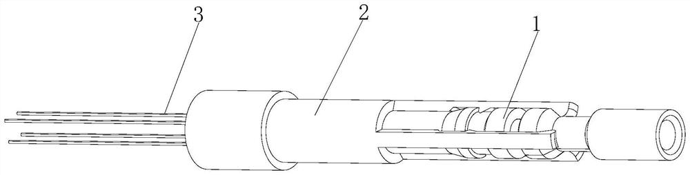
[0026] like Figure 1 to Figure 4 As shown, the optical fiber coupling system of the present invention includes an optical fiber connector 1 and an adapter 2 .

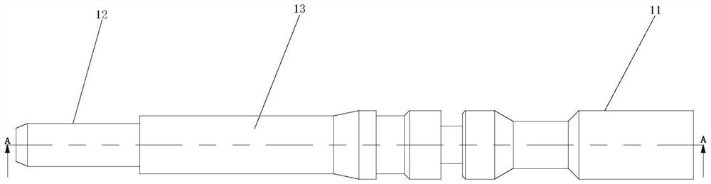
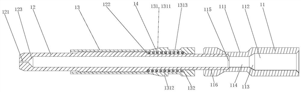
[0027] The optical fiber connector 1 includes an optical fiber end tube 11 , an optical fiber connecting tube 12 and an outer movable sleeve 13 . The optical fiber end tube 11 , the optical fiber connection tube 12 and the outer movable sleeve 13 are all hollow tubular parts, and the optical fiber end tube 11 , the optical fiber connection tube 12 and the outer movable sleeve 13 are all metal parts with high strength.

[0028] The optical fiber end tube 11 is a hollow tubular structure. The outer wall of the left end of the optical fiber end tube 11 is provided with a second assembly portion 111. The second assembly portion 111 is an annular groove, and the left and right sides of the annular groove are both. Tapered slope, the diameter of the tapered slope gradually increases from the bottom of the annular groove to...

Embodiment 2

[0035] like Figure 5-Figure 8 As shown, the optical fiber coupling system of the present invention includes an optical fiber connector 1 and an adapter 2 .

[0036] The optical fiber connector 1 includes an optical fiber end tube 11 , an optical fiber connecting tube 12 and an outer movable sleeve 13 . The optical fiber end tube 11 , the optical fiber connection tube 12 and the outer movable sleeve 13 are all hollow tubular parts, and the optical fiber end tube 11 , the optical fiber connection tube 12 and the outer movable sleeve 13 are all metal parts with high strength.

[0037] The fiber end tube 11 is a hollow tubular structure, and the inner hole of the fiber end tube 11 is a first cylindrical hole, a first conical hole, a second cylindrical hole, and a second conical hole from right to left. The diameter of the first conical hole gradually decreases from right to left, the diameter of the second conical hole gradually increases from right to left, and the diameter of ...


PUM


Abstract

The invention discloses an optical fiber coupling system, which includes an optical fiber connector and an adapter. The optical fiber connector includes an optical fiber end tube, an optical fiber connecting tube and an outer movable sleeve. The right end of the optical fiber connecting tube is fixedly connected to the optical fiber end tube. The optical fiber connecting tube The left end of the optical fiber outlet is provided with an optical fiber outlet, and the outer movable sleeve is slidably matched with the optical fiber connection tube. A stepped surface is provided on the outer wall of the optical fiber connection tube. Diameter, there is a limit surface on the right end of the outer movable sleeve, the limit surface is set opposite to the step surface, a compression spring is arranged between the limit surface and the step surface, and an assembly part is arranged on the outer wall of the optical fiber connector , the adapter includes a left pipe part and a right connecting part, and the connecting part is fixedly connected with the fitting part on the optical fiber connector. The optical fiber coupling system of the present invention has simple structure, easy assembly and disassembly, and the diameter of the optical fiber coupling system is greatly reduced, which can increase the connection density.

Description

technical field [0001] The invention relates to the field of communication equipment, in particular to an optical fiber coupling system. Background technique [0002] Optical fiber communication is a commonly used communication method in communication. Because optical fiber communication has low loss and high transmission rate, the use of optical fiber communication is becoming more and more extensive. In optical fiber communication, fiber coupling system is an important connecting device. The existing optical fiber coupling system is usually made of plastic material, has a rectangular structure, and has a large diameter. When connecting on the optical fiber connection equipment panel, the connection density is low, and the number of optical fibers that can be plugged at the same time is small. For example, the patent document with publication number CN108572417A discloses an optical fiber coupling system, and specifically discloses, including an inner shell module and an o...

Claims


Application Information

Patent Timeline
Patent Type & Authority Patents(China)
IPC IPC(8): G02B6/38
CPCG02B6/3825G02B6/3833
Inventor 邓军涛张玉波邓英霞祝传德
Owner 埃尔发光电智能科技(常州)有限公司
Why Eureka
Try Eureka