Rail laying device and method for rail traffic engineering construction

A rail transit engineering and laying device technology, which is applied in the direction of track, track laying, track maintenance, etc., can solve the problems that affect the progress of laying, the difficulty of manual assistance, time-consuming and other problems, and achieve the effect of speeding up the progress of laying

Active Publication Date: 2021-04-20
武汉锐进铁路发展有限公司
View PDF17 Cites 0 Cited by
  • Summary
  • Abstract
  • Description
  • Claims
  • Application Information

AI Technical Summary

Problems solved by technology

[0004] (1) The existing track laying device does not have a device for automatically aligning two tracks during laying work, and usually requires manual or other mechanical assistance to align and connect the tracks. These two methods are difficult to manually assist, and The degree of industrial accidents is high. In addition, the use of additional mechanical devices to assist movement will consume additional power, and it is not conducive to use under conditions of limited space;
[0005] (2) The existing track laying device does not provide a device for direct detection of the track joints during laying work. It needs to be manually inspected section by section after the laying is completed. The manual inspection method has a large workload and cannot be timely Abnormalities are detected, and remedial measures cannot be taken in time;
[0006] (3) During the continuous replenishment process of the assembled rail row, its final placement position will be shifted to some extent. Therefore, in the subsequent moving process, the best balance point needs to be continuously adjusted according to its placement position. Therefore, the progress of laying is affected, and the subsequent connection process also requires constant adjustment, which not only consumes time but also affects the work of rail splicing

Method used


Image

  • Rail laying device and method for rail traffic engineering construction
  • Rail laying device and method for rail traffic engineering construction
  • Rail laying device and method for rail traffic engineering construction

Examples


example 1

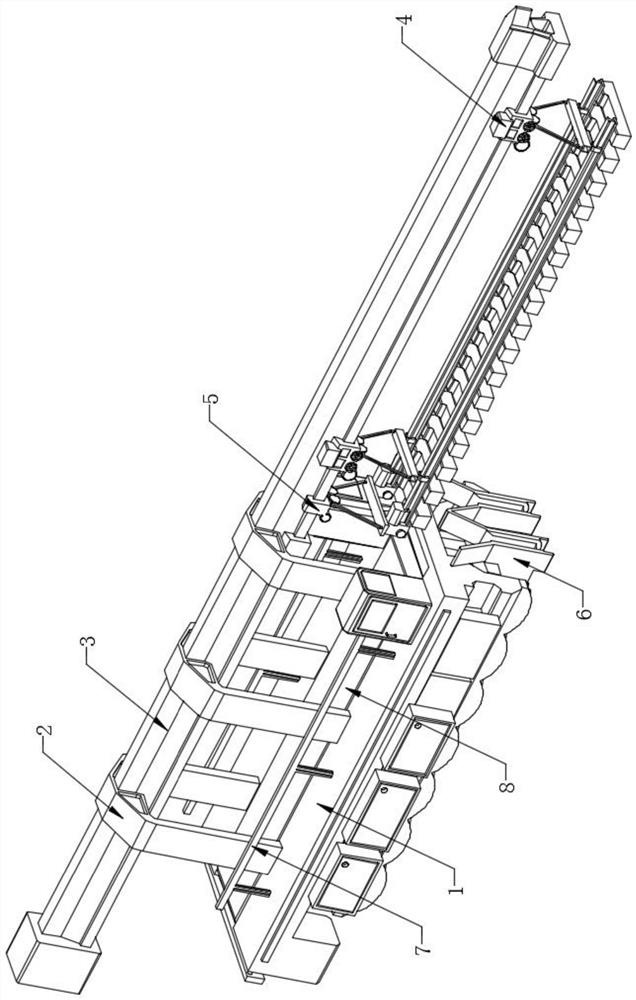
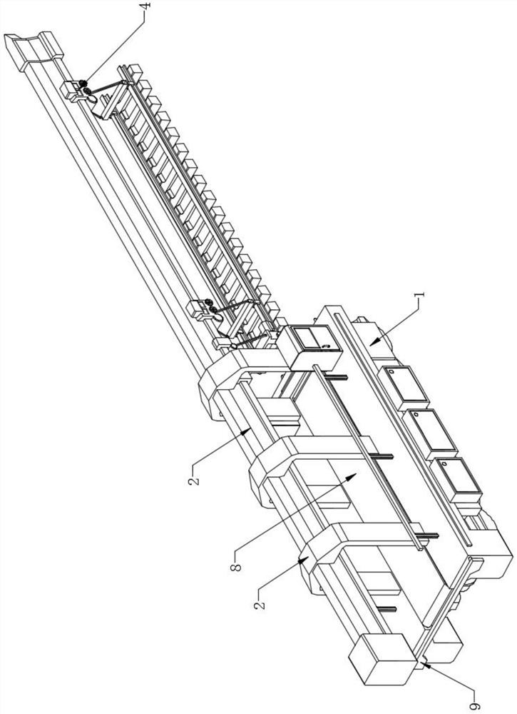
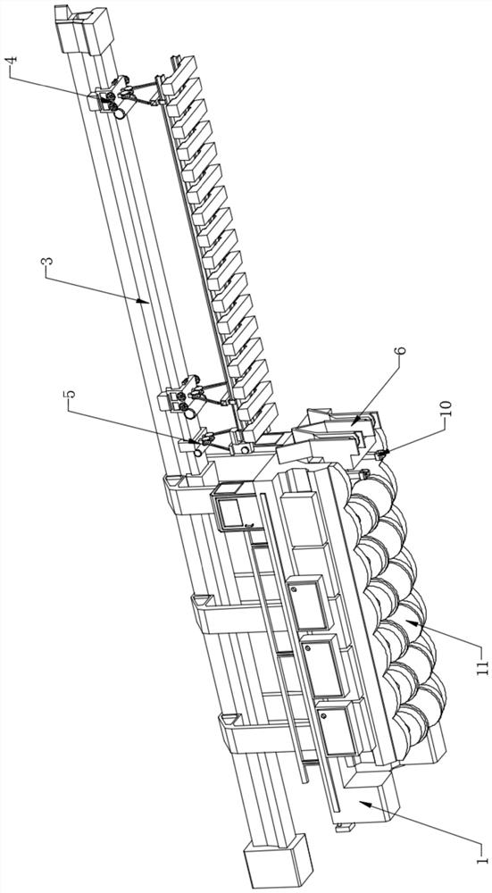
[0042] Example 1: Please also refer to Figure 1-9 , figure 1 It is a schematic three-dimensional structure diagram of the front view of the track laying device for rail transit engineering construction in an embodiment of the present invention, figure 2 for figure 1 The schematic diagram of the rear-view three-dimensional structure shown in the embodiment, image 3 for figure 1 The schematic diagram of the three-dimensional structure shown in the embodiment, Figure 4 for figure 1 Schematic diagram of the three-dimensional structure of the tail end guide assembly shown in the embodiment, Figure 5 for figure 1 The cross-sectional structural schematic diagram of the tail end guide assembly shown in the embodiment, Image 6 for figure 1 The three-dimensional schematic diagram of the positioning seat structure shown in the embodiment, Figure 7 for figure 1 The structural schematic diagram of the joint detection assembly shown in the embodiment, Figure 8 for figure...

example 2

[0051] Example 2: The laying method of the track laying device for the construction of the rail transit project, the details are as follows Figure 10 shown, Figure 10 for figure 1 The flow chart of the laying method of the track laying device for rail transit engineering construction shown in the embodiment,

[0052] S1: Move before connection: The moving wheel combination unit drives the track laying machine to move to one end of the single-segment track, and the two single-segment track conveyors move to the top of the track-laying machine, respectively fixing the head and tail ends of the single-segment track. The clamp seat inside the tail end guide assembly fixes the tail end of the single-segment track.

[0053] S2: Transporting single-section track: Two single-section track conveyors drive a section of track to move along the direction of the transport track. At this time, the tail end guide assembly moves along with it. When the guide box moves directly above the p...


PUM


Abstract

The invention discloses a rail laying device and method for rail traffic engineering construction, and the device comprises a rail laying machine, a tail end guide assembly, a positioning seat structure, a transportation limiting assembly, and a connector detection assembly. The tail end guide assembly is movably arranged above the rail laying machine. The positioning seat structure is fixedly arranged on one side of the rail laying machine, the transportation limiting assembly is fixedly arranged in the rail laying machine, and the connector detection assembly is fixedly arranged on the lower portion in the rail laying machine. Therefore, the effect that the ends of the two sections of rails are rapidly aligned and connected can be achieved, the laying progress is accelerated, and manual guiding of an operator is not needed; and besides, after the guide connection work is realized, the separation from a track panel is autonomously realized, then the splicing detection work is completed, the connection detection result is provided in time, and finally, a single-section track is conveniently and quickly fixed to the optimal balance position.

Description

technical field [0001] The invention relates to the technical field of track laying equipment, in particular to a track laying device and a laying method for rail transit engineering construction. Background technique [0002] Track laying machinery refers to special machinery for laying track and ballast. There are two types: one is to transport the rail row assembled at the base to the laying site by a special train, and then use a track laying machine to lay the rail row on the track. On the bed, the other is a track laying unit consisting of a traction power part, a main machine of a rail laying machine, a sleeper rotating gantry crane, a double sleeper, and a rail transport vehicle. , and then put the rail on the rail bearing platform of the sleeper to complete the rail laying operation; [0003] However, the existing track laying devices have the following drawbacks: [0004] (1) During the laying work of the existing track laying device, there is no device for autom...

Claims


Application Information

Patent Timeline
Patent Type & Authority Applications(China)
IPC IPC(8): E01B29/02E01B35/00
Inventor 张海龙
Owner 武汉锐进铁路发展有限公司
Why Eureka
Try Eureka