Method of positioning damaged fuel assembly

A fuel assembly, damaged technology, applied in the field of nuclear power, can solve the problems of large radiation risk and industrial safety risk, cost, and large manpower

Inactive Publication Date: 2020-10-20
JIANGSU NUCLEAR POWER CORP
View PDF4 Cites 2 Cited by
  • Summary
  • Abstract
  • Description
  • Claims
  • Application Information

AI Technical Summary

Problems solved by technology

[0003] At present, in various nuclear power units in service at home and abroad, the method for checking whether there are damaged fuel assemblies in the core during power operation is relatively mature, but it is still difficult to determine the position of damaged fuel assemblies in the core during power operation
The general way to find out the location of damaged fuel assemblies is to use the method of leaking at the side of the pool to check one by one after the unit is shut down, which requires a lot of manpower, material resources and construction period, and there are relatively large radiation risks and industrial safety risks

Method used


Image

  • Method of positioning damaged fuel assembly
  • Method of positioning damaged fuel assembly
  • Method of positioning damaged fuel assembly

Examples


Embodiment 1

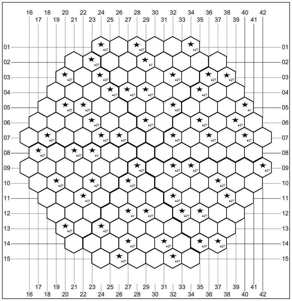
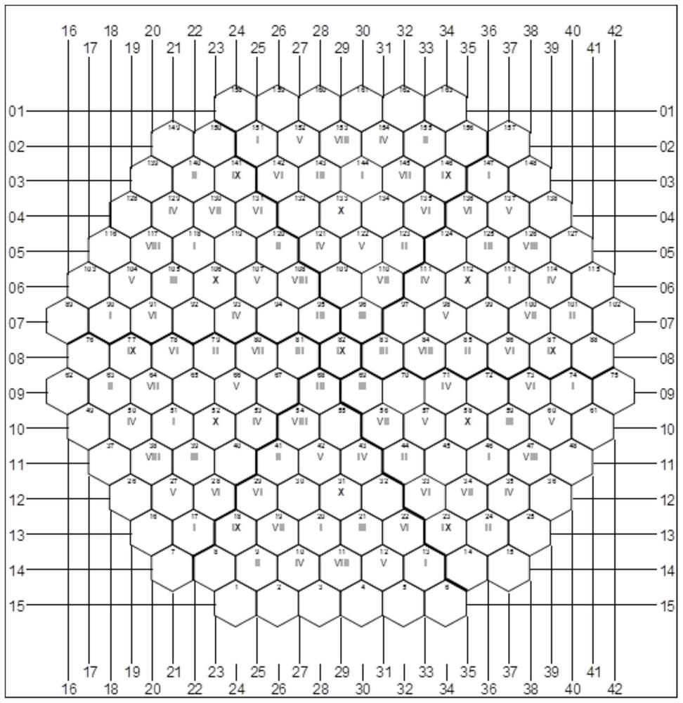
[0052] The layout of the detectors of the nuclear power unit core measurement system is as follows: figure 2 , the control rod bundles are arranged as image 3 .

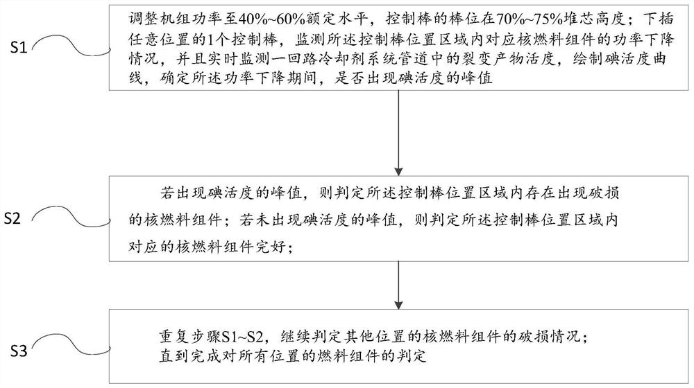
[0053]Adjust the power level of the unit and the position of the control rods to ensure that during the process of lowering the control rods at local positions, the distortion of the core power distribution will not cause relevant protection actions, and the position of the control rods is within the limit range specified for the safe operation of the unit; In this implementation example, the unit power is controlled at 50% of the rated level, and the position of the control rods is at 75% of the core height.

[0054] By inserting the control rod at a certain position of the core, the core measurement system is used to monitor the power drop of the components at this position.

[0055] Utilize the fuel damage online detection and analysis system to monitor the fission product activity in the primary circuit coola...

Embodiment 2

[0061] Adjust the power level of the unit and the position of the control rods to ensure that during the process of lowering the control rods at local positions, the distortion of the core power distribution will not cause relevant protection actions, and the position of the control rods is within the limit range specified for the safe operation of the unit; In this implementation example, the unit power is controlled at 50% of the rated level, and the position of the control rods is at 75% of the core height.

[0062] By inserting the control rod at a certain position of the core, the core measurement system is used to monitor the power drop of the components at this position.

[0063] The online fuel damage detection and analysis system was used to monitor the fission product activity in the pipeline of the primary coolant system in real time, and the iodine activity curve was drawn to determine that there was no iodine peak in the fuel assembly at this position during the po...


PUM


Abstract

The invention relates to the field of nuclear power, in particular to a method for positioning a damaged fuel assembly. The method for positioning a damaged fuel assembly comprises the following steps: adjusting the unit power to 40%-60% of a rated level, controlling the rod position of a control rod to be 70%-75% of the height of a reactor core; inserting one control rod downwards, monitoring thepower reduction condition of the corresponding fuel assembly in the control rod position area, monitoring the fission product activity in a primary loop coolant system pipeline in real time, drawingan iodine activity curve, and determining whether a peak value of iodine activity occurs or not during the power reduction period; if the peak value of the iodine activity appears, judging that a damaged fuel assembly exists in the control rod position area; if the peak value of the iodine activity does not appear, judging that the fuel assembly in the control rod position area is intact; repeating the steps, and continuously judging the damage conditions of the fuel assemblies at other positions. According to the method, the pressurized water reactor nuclear power unit can locate the positionof the damaged fuel assembly during power operation, and the discrimination efficiency is high.

Description

technical field [0001] The invention relates to the field of nuclear power, in particular to a method for locating damaged fuel assemblies. Background technique [0002] As the first safety barrier of nuclear power plants, the integrity of fuel assemblies is directly related to the safety, reliability and economy of nuclear power plants. Although the reliability of the fuel assemblies used in commercial nuclear power units has been greatly improved with the development of nuclear power technology, in the actual reactor operation, especially with the scale development of nuclear power units, the fuel assemblies are affected Losses are also increasing. [0003] At present, in various nuclear power units in service at home and abroad, the methods for checking whether there are damaged fuel assemblies in the core during power operation are relatively mature, but it is still difficult to determine the location of damaged fuel assemblies in the core during power operation. The g...

Claims


Application Information

Patent Timeline
Patent Type & Authority Applications(China)
IPC IPC(8): G21C17/04
CPCG21C17/04Y02E30/30
Inventor 叶刘锁潘泽飞杨晓强刘健王伟姜宇马旭东金涛
Owner JIANGSU NUCLEAR POWER CORP
Why Eureka
Try Eureka