Hydrogen removal system of closed container

A closed container and hydrogen system technology, applied in the field of safety production, can solve problems such as regular purging, hidden safety hazards, huge system safety risks and economic risks

Active Publication Date: 2020-10-20
SHANGHAI POWER EQUIP RES INST
View PDF22 Cites 0 Cited by
  • Summary
  • Abstract
  • Description
  • Claims
  • Application Information

AI Technical Summary

Problems solved by technology

Taking the battery system as an example, when the battery is charging and storing energy, a certain amount of hydrogen gas will be released in the charging reaction. If the battery system is a closed system, the whole system can be equivalent to a closed container in which hydrogen evolution reactions occur continuously. When stored in the container When the concentration of hydrogen reaches a certain level, it will form a safety hazard and endanger the safe operation of the entire battery system. If the hydrogen in the closed system cannot be processed in a timely and effective manner, the system will suffer huge safety and economic risks.
At present, to solve the problem of hydrogen accumulation in the closed system, most of the measures taken are to use nitrogen purging to reduce the hydrogen concentration in the container. This method has a large loss of nitrogen, and the hydrogen concentration inside the container is not easy to monitor, so it can only be purged periodically. , will cause a large waste of
In addition, there is also a method to directly extract the gas phase space in the closed container and discharge it to the atmosphere for dilution. This treatment will also discharge other polluting gases generated by the electrochemical system into the atmosphere, resulting in greater air pollution and material waste.
Therefore, the measures that can be taken at present have certain defects. For the problem of hydrogen accumulation in closed systems, this technical field needs a low-cost, convenient control, and efficient and environmentally friendly system for eliminating hydrogen.

Method used


Image

  • Hydrogen removal system of closed container
  • Hydrogen removal system of closed container
  • Hydrogen removal system of closed container

Examples


Embodiment Construction

[0020] In order to make the present invention more obvious and understandable, the preferred embodiments are described in detail as follows in conjunction with the accompanying drawings:

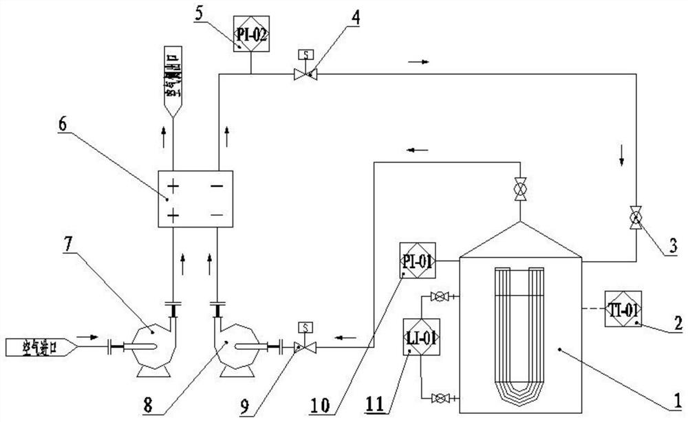
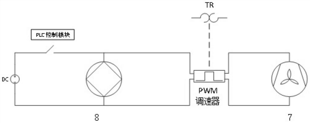
[0021] like Figure 1-3 As shown, the present invention provides a hydrogen removal system for a closed container, including a closed container 1, a fuel cell hydrogen side outlet solenoid valve 4, a fuel cell hydrogen side outlet pressure sensor 5, a hydrogen fuel cell 6, a blower 7, a hydrogen pump 8, The fuel cell hydrogen side inlet solenoid valve 9, the closed container pressure sensor 10 and the electrical control system; the closed container 1 is connected to the hydrogen fuel cell 6 through the hydrogen pump 8, and the hydrogen fuel cell 6 is connected to the closed container through the fuel cell hydrogen side outlet solenoid valve 4 1 connection; the hydrogen fuel cell 6 is provided with a blower 7, one end of the blower 7 is provided with an air inlet port, and the hydrogen fuel c...


PUM


Abstract

The invention relates to a hydrogen removal system of a closed container, and belongs to the technical field of safety production. The system comprises a closed container, a fuel cell hydrogen side outlet electromagnetic valve, a fuel cell hydrogen side outlet pressure sensor, a hydrogen fuel cell, an air blower, a hydrogen pump, a fuel cell hydrogen side inlet electromagnetic valve, a closed container pressure sensor and an electrical control system. The hydrogen removal system for solving the hydrogen accumulation problem of the closed system is designed by utilizing the hydrogen reaction capacity of the hydrogen fuel cell. According to the invention, according to change of the hydrogen concentration in the closed container, the operation state of the hydrogen removal system is adjustedin real time, the system can be opened to remove hydrogen as long as the concentration exceeds a warning value until the concentration of hydrogen in the container is reduced to a safe range, the safety risk caused by hydrogen accumulation in the container is effectively reduced, and safe and stable operation of a closed electrochemical system is facilitated.

Description

technical field [0001] The invention relates to a hydrogen removal system for a closed container, belonging to the technical field of safe production. Background technique [0002] In the field of electrochemical industry, in addition to obtaining the required substances or realizing the necessary functions, many side reactions will occur during the relevant production operations, among which the hydrogen evolution reaction is a type of reaction that must be paid attention to; the product of this reaction, hydrogen It is combustible and explosive. If the hydrogen evolution reaction occurs in a closed system, the continuously produced hydrogen will gradually accumulate and form a safety hazard, causing the closed system to bear greater safety and economic risks. Therefore, in the electrochemical industrial production process where hydrogen evolution reaction may occur, how to remove the continuously produced and accumulated hydrogen and reduce the risk of system operation is ...

Claims


Application Information

Patent Timeline
Patent Type & Authority Applications(China)
IPC IPC(8): H01M8/0662H01M8/04701H01M8/04746H01M8/04791
CPCH01M8/04708H01M8/04738H01M8/04761H01M8/04798H01M8/0662Y02E60/50Y02P70/50
Inventor 俞高伟申鹏韩峰张辉吴珂科
Owner SHANGHAI POWER EQUIP RES INST
Why Eureka
Try Eureka