Thoracic cavity drainage automatic control device

An automatic control device and thoracic cavity technology, applied in the direction of suction equipment, hypodermic injection equipment, pumping and pumping systems, etc., can solve problems such as endangering the life of patients, large errors, and failure to follow the doctor's expected method

Inactive Publication Date: 2020-10-23
德州飚丰信息技术有限公司
View PDF0 Cites 0 Cited by
  • Summary
  • Abstract
  • Description
  • Claims
  • Application Information

AI Technical Summary

Problems solved by technology

[0004] During the drainage of a large amount of pleural effusion, there are often specific requirements for clinical parameters such as daily drainage times, each drainage volume, and drainage speed according to the condition of the case. In actual clinical operations, the clinical parameters during the drainage process are usually It is realized by the subjective control of the medical staff or the patient's family members. The current artificial control method has certain disadvantages. On the one hand, the drainage process is often caused by misunderstanding in the oral communication of the doctor's order or the negligence of the operator. Failure to perform as expected by the doctor may cause discomfort and injury to the patient due to improper drainage, and even endanger the life of the patient. On the other hand, the real-time drainage volume and drainage speed during the drainage process are usually judged by human observation. Larger size also makes it difficult to guarantee the drainage effect. At the same time, the current control method will obviously increase the burden on the medical staff and the patient's family members.

Method used


Image

  • Thoracic cavity drainage automatic control device
  • Thoracic cavity drainage automatic control device
  • Thoracic cavity drainage automatic control device

Examples


Embodiment 1

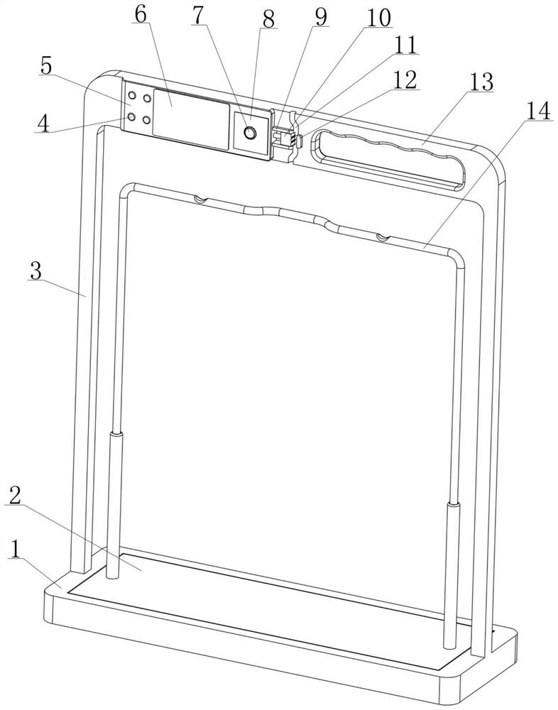
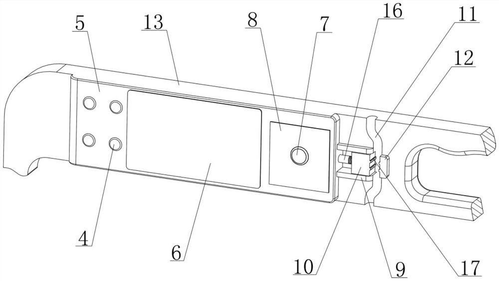
[0032] see Figure 1-4 As shown, the chest drainage automatic control device disclosed in this embodiment is composed of a weighing bracket, a flow rate adjustment mechanism, a controller 5 and a power supply assembly;

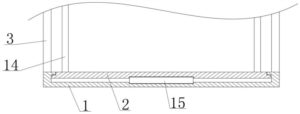
[0033] Among them, see figure 1 , 2, 5, the weighing type support includes a weighing mechanism with weight measurement function formed by the weighing table 2, the load cell 15 and the base 1, which are sequentially matched up and down, and the weighing output of the load cell 15 is The signal can reflect the weight of the object above the weighing platform 2; a gantry frame is fixed on the base 1, and the beam 13 at the upper end of the gantry frame is horizontal, and the side wall of the beam 13 is provided with a vertical extension for accommodating and clamping the arrangement of the drainage tube 19 Slot 11; a suspension device 14 for hanging the drainage bag 18 and making the drainage bag 18 below the beam 13 is fixed on the weighing platform 2; the s...

Embodiment 2

[0052] see Figure 5 As shown, the existing drainage bag 18 is made of soft plastic material and has the characteristics of easy deformation, but when it is used clinically with the chest drainage automatic control device disclosed in Example 1, it is suspended from the top During the drainage process, the weight of the effusion is all borne by the drainage bag 18. As the effusion in the drainage bag 18 gradually increases, the pressure in the drainage bag 18 gradually increases, so that the maximum drainage speed that can be achieved in the drainage process Inhomogeneous before and after, and the flow rate is slow in the middle and late stages of the drainage process, and the drainage efficiency is low; based on the above technical problems, this embodiment has the following improvements on the basis of the structure of the chest drainage automatic control device disclosed in Example 1:

[0053] that is, Figure 9 As shown, the suspension device 14 can be stretched in the vert...

Embodiment 3

[0057] see Figure 7 As shown, in the clinical use of the chest drainage automatic control device disclosed in the foregoing embodiments, each time the drainage is suspended or the entire drainage operation is completed, the drainage tube 19 is squeezed by the flow rate adjustment mechanism and is blocked. To separate the drainage tube 19 from the placement groove 11, it is necessary to drive the movable clamp block 10 away from the fixed clamp block 12 by means of the manual key 7, so that the flow rate adjustment mechanism can release the squeezing effect on the drainage tube 19, but if the manual key 7, When any component in the controller 5 and the power supply fails, the movable clamp block 10 cannot move as expected, so that the drainage tube 19 cannot be separated from the placement groove 11 smoothly;

[0058] Considering that the above defects bring certain inconvenience to the clinical operation, this embodiment also has the following improvements on the basis of the...


PUM


Abstract

The invention relates to the field of medical instruments, and discloses a thoracic cavity drainage automatic control device. The device is composed of a weighing type support, a flow rate adjusting mechanism, a controller and a power supply assembly; the weighing type support is provided with a containing groove used for containing and clamping a drainage tube and a weighing sensor used for weighing; the flow rate adjusting mechanism comprises a fixed clamping block and a movable clamping block, and the purposes of controlling on-off of the drainage tube and adjusting the flow rate of fluid can be achieved by extruding the drainage tube in the containing groove; the controller can correspondingly control the flow speed adjusting mechanism based on preset drainage parameters and the changestate of the real-time weight data in the drainage period; and the power supply assembly is used for providing working current for power consumption elements. The thoracic cavity drainage automatic control device adopts an intelligent design, can realize automatic control of timing drainage, quantitative drainage and constant-speed drainage by being matched with an existing conventional drainageassembly for use, improves the safety and stability of drainage operation, saves manpower, guarantees the drainage effect, and is convenient and fast to use.

Description

[0001] The present invention is a divisional application of the invention patent application with application number 2018111350223 submitted on September 28, 2018. technical field [0002] The invention relates to the technical field of medical instruments, in particular to an automatic control device used in thoracic drainage. Background technique [0003] Normal people have 3ml~15ml of fluid in the pleural cavity, which acts as a lubricant during respiratory movement. These fluids are continuously formed and absorbed to maintain a dynamic balance. If this balance is destroyed by disease, the fluid in the pleural cavity will form too quickly. Or if the absorption is too slow, pleural effusion will form, which is also called pleural effusion clinically. Pleural effusion is a relatively common clinical disease. Various lung diseases such as inflammation, malignant tumors, tuberculosis, fungi, etc. can cause pleural effusion, while extrapulmonary diseases such as heart failure...

Claims


Application Information

Patent Timeline
Patent Type & Authority Applications(China)
IPC IPC(8): A61M1/00
CPCA61M1/0023A61M2205/3334A61M1/74
Inventor 王才丰
Owner 德州飚丰信息技术有限公司
Why Eureka
Try Eureka