
Multi-functional breathing nursing device for respiratory medicine department

A technology for respiratory medicine and nursing devices, applied in the field of respiratory medicine, which can solve problems such as poor connection stability of ventilators and reduced service life of ventilators

Pending Publication Date: 2020-10-23
曲阜市人民医院
View PDF8 Cites 2 Cited by
  • Summary
  • Abstract
  • Description
  • Claims
  • Application Information

AI Technical Summary

Problems solved by technology

However, due to the vertical movement of the ventilator, the connecting circuit and the trachea of ​​the ventilator also have a certain expansion and contraction movement, which makes the connection stability of the ventilator poor, and requires frequent maintenance of the connecting circuit and the trachea respectively. The connection of the ventilator, the service life of the ventilator is greatly reduced

Method used

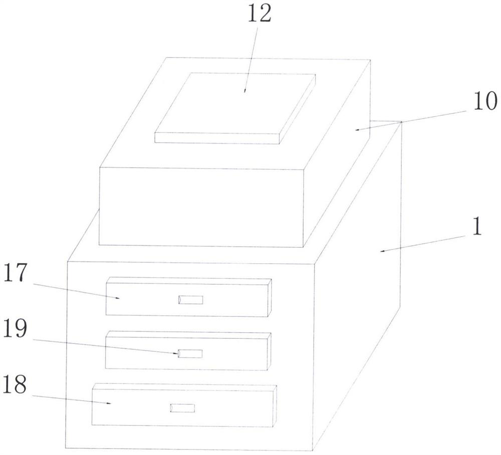
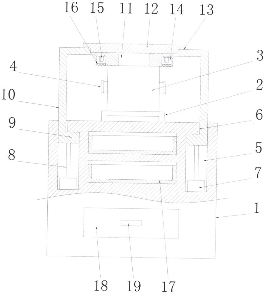

Image

  • Multi-functional breathing nursing device for respiratory medicine department
  • Multi-functional breathing nursing device for respiratory medicine department
  • Multi-functional breathing nursing device for respiratory medicine department

Examples


Embodiment 1

[0028] See Figure 1-2 , a multifunctional respiratory care device used in respiratory medicine, comprising a seat box 1, a base 2 is provided in the middle of the top of the seat box 1, the base 2 is a U-shaped structure, and the top of the base 2 is fixedly installed There is a ventilator body 3, the side end of the ventilator body 3 is evenly provided with a number of air supply ports 4, the top of the ventilator body 3 is fixedly connected to the top box 11, and the top of the top box 11 is fixedly connected to the sealing plate 12, so The bottom edge of the sealing plate 12 is provided with a card cavity 13, the card cavity 13 is an annular structure, the upper edge of the seat box 1 is embedded with a sealing dynamic cavity 5, and the sealing dynamic cavity 5 is an annular structure, and the sealing The top of the moving chamber 5 connects through the sliding hole 6, the sliding hole 6 is an annular hole, and the inner cavity bottom wall of the sealed moving chamber 5 is...

Embodiment 2

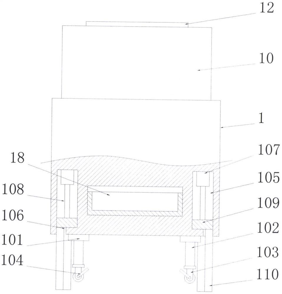
[0032] See image 3 The difference from Embodiment 1 is that: the bottom end of the seat box 1 is evenly provided with several shock absorbing plates 101, the bottom ends of the shock absorbing plates 101 are fixedly connected to the leg rods 102, and the bottom ends of the leg rods 102 The end is fixedly connected with the universal wheel 103, the universal wheel 103 is equipped with a foot brake 104, and the seat box 1 is supported by the universal wheel 103 with the leg bar 102, which can greatly improve the convenience of the transfer and transportation of the whole device; and through The shock absorbing plate 101 is provided, which can reduce the operating vibration of the entire device and effectively ensure the safety of the entire device during transportation;

[0033] The lower edge of the seat box 1 is evenly embedded with a number of conversion moving chambers 105, the bottom ends of the conversion moving chambers 105 are connected through the connection through ho...

Embodiment 3

[0035] See Figure 4 The difference from Embodiment 1 is that the second drawer 18 has the same structure as the first drawer 17, the second drawer 18 includes a drawer box 181, and the drawer box 181 is a box structure with an open top, One end of the drawer box 181 is fixedly connected with a baffle plate 182 matched with the seat box 1. The drawer box 181 and the baffle plate 182 are integrally formed. The handle groove 19 is arranged on the baffle plate 182. The inner cavity bottom of box 181 is provided with dividing plate 184, and described dividing plate 184 is to select transparent glass to make for use, and dividing plate 184 divides the inner cavity of drawer box 181 into irradiation cavity 185 and storage cavity 186, and described irradiation cavity 185 Located below the storage chamber 186, the inner chamber of the irradiation chamber 185 is equipped with a second ultraviolet lamp 18, and the front and rear side walls of the inner chamber of the storage chamber 186...


PUM


Abstract

The invention discloses a multi-functional breathing nursing device for respiratory medicine department. The multi-functional breathing nursing device comprises a seat box, wherein a base is arrangedin the center of the top end of the seat box, a breathing machine body is fixedly mounted at the top end of the base, a plurality of air supply openings are uniformly formed in the side end of the breathing machine body, a top box is fixedly connected to the top end of the breathing machine body, a sealing plate is fixedly connected to the top end of the top box, and a clamping cavity is arrangedat the edge of the bottom end of the sealing plate; and a sealing movable cavity is formed in the edge of the upper part of the seat box in an embedding manner, a sliding hole is in penetrating connection to the top end of the sealing movable cavity, a plurality of air cylinders are uniformly arranged on the bottom wall of an inner cavity of the sealing movable cavity, a first lifting board is jointly and fixedly connected to the top ends of air pressure rods on the all air cylinders, and a sleeving box which cooperates with the sliding holes and the clamping cavity respectively is fixedly connected to the top end of the first lifting board. The whole sealing and unfolding process of the multi-functional breathing nursing device is completed through lifting of the sleeving box, while the breathing machine body is fixed and stationary, so that stability of a circuit and an air pipe connected with the breathing machine body can be guaranteed, and the service life of the breathing machinebody can be substantially prolonged.

Description

technical field [0001] The invention relates to the technical field of respiratory medicine, in particular to a multifunctional respiratory care device for respiratory medicine. Background technique [0002] The Department of Respiratory Medicine mainly focuses on diseases related to the respiratory system, as follows: 1. Infectious diseases: pneumonia, bronchitis, rhinitis, etc.; Obstructive lung disease, bronchial asthma; 3. Interstitial lung disease: such as common pulmonary interstitial fibrosis, various types of interstitial lung disease; 4. Lung cancer; 5. Related diseases: such as gastroesophageal reflux, postnasal Drip syndrome, pulmonary vascular disease. [0003] In order to facilitate the use of the existing ventilator, its sealed storage is to use the lifting mechanism to raise or lower the ventilator from the sealed box. This lifting and storage structure greatly improves the convenience of using and storing the ventilator. However, due to the vertical movemen...

Claims


Application Information

Patent Timeline
Patent Type & Authority Applications(China)
IPC IPC(8): A61M16/00A61B50/30A61B50/18A61L2/10F16M1/00F16M7/00
CPCA61M16/00A61M16/0003A61B50/18A61B50/30A61L2/10F16M1/00F16M7/00A61M2209/084A61B2050/005A61B2050/185A61L2202/24
Inventor 孔爱华
Owner 曲阜市人民医院
Learn More