High-pressure copper bar processing technique capable of overcoming punching corner collapse

A processing technology and high-pressure technology, applied in the field of high-voltage copper bar stamping, can solve problems such as stamping slump process defects

Active Publication Date: 2020-10-23
宁波峰梅精密科技有限公司
View PDF9 Cites 3 Cited by
  • Summary
  • Abstract
  • Description
  • Claims
  • Application Information

AI Technical Summary

Problems solved by technology

[0005] The technical problem to be solved by the present invention is to provide a high-voltage copper bar processing technology that overcomes stamping slump angle, which can well solve the problem of stamping sag angle process defects existing in the above-mentioned existing high-voltage copper bar stamping process

Method used


Image

  • High-pressure copper bar processing technique capable of overcoming punching corner collapse
  • High-pressure copper bar processing technique capable of overcoming punching corner collapse
  • High-pressure copper bar processing technique capable of overcoming punching corner collapse

Examples


Embodiment 1

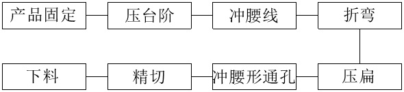
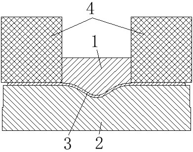
[0036] A high-voltage copper bar 3 processing technology for overcoming stamping slump, comprising the following steps:

[0037] Product fixing: Fix the high-voltage copper bar 3 to the lower mold 2.

[0038] The processing technology of the high-voltage copper bar 3 also includes a pressing step 8 arranged after the product is fixed and before bending, and step marks are pressed on the outer edges of both ends of the high-voltage copper bar 3, and then the steps 8 are punched out along the pressed step marks.

[0039] The processing technology of the high-voltage copper bar 3 also includes setting the waist line 9 after the product is fixed and before bending, and the waist line 9 required by the product is punched out at both ends of the middle part of the high-voltage copper bar.

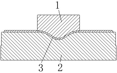
[0040] Bending: Utilize the pressing of the upper mold 1 and the lower mold 2 to bend the high-voltage copper bar 3 from the middle. At this time, the high-voltage copper bar 3 has a structure wi...

Embodiment 2

[0053] The present embodiment provides a high-voltage copper bar without sag produced by the above-mentioned processing technology.

[0054] refer to Figure 7 and Figure 8 , a high-voltage copper bar without slump, comprising a plate-shaped conductive body 11 and connecting parts 12 respectively arranged at both ends of the conductive body 11, the material of the conductive body 11 is metal, and preferably flexible copper, so as to facilitate For processing such as bending and stamping, the connection part 12 is provided with a horizontal connection surface, and the two sides of the connection part 12 are symmetrically provided with side end surfaces 13, and the side end surfaces 13 are arranged perpendicular to the connection surface. After being symmetrically stacked, it is fixed on the carrier and sealed with glue. The connecting part 12 is provided with a waist-shaped hole 16, and the connecting piece passes through the waist-shaped hole 16 and cooperates with the exter...


PUM


Abstract

The invention provides a high-pressure copper bar processing technique capable of overcoming punching corner collapse, comprising the following steps: product fixation: fixing a high-pressure copper bar on a lower mold; bending: bending the high-pressure copper bar from the middle portion by pressing an upper mold and the lower mold; flattening: flattening straight portions of both ends of the bent high-pressure copper bar by using an upper mold flattening punch; precise cutting: precisely cutting the straight portions of both ends of the flattened high-pressure copper bar by using a precise cutting punch; and product falling: taking out the high-pressure copper bar from the lower mold after precise cutting and burr removal. The high-pressure copper bar processing technique capable of overcoming punching corner collapse provided by the invention performs the precise cutting process after flattening and thinning the high-pressure copper bar, and vertically cuts off the part extending outwards by precise cutting to effectively prevent the corner collapse problem of the high-pressure copper bar; and finally, during glue injection, the glue leakage is prevented, and the contact area ofthe high-pressure copper bar is fully guaranteed, so that the electric performance of the high-pressure copper bar after glue injection is guaranteed.

Description

technical field [0001] The invention relates to the field of stamping of high-voltage copper bars, in particular to a high-voltage copper bar processing technology for overcoming stamping slump. Background technique [0002] High-voltage copper bars are important accessories in new energy vehicles. Generally, high-voltage copper bars need to be used in combination with injection glue. There are many problems with glue. [0003] In the existing ordinary stamping manufacturing of high-voltage copper bars, there will be a process defect of stamping sag in the front of the stamping direction of the stamping cut edge of the stamped product; and the existence of stamping slump will lead to insert injection molding of high-voltage copper bars. When the sealant overflows and the contact area of ​​the high-voltage copper busbar decreases, it will affect the performance of the high-voltage copper busbar after insert injection molding. Contents of the invention [0004] (1) Technic...

Claims


Application Information

Patent Timeline
Patent Type & Authority Applications(China)
IPC IPC(8): B21D5/02B21D28/26B21D35/00
CPCB21D5/02B21D28/26B21D35/001B21D35/002
Inventor 杨伟章德道陈彬
Owner 宁波峰梅精密科技有限公司
Why Eureka
Try Eureka