Eureka AIR delivers breakthrough ideas for toughest innovation challenges, trusted by R&D personnel around the world.

Steel belt sample control device for sampling

A technology for controlling devices and samples, applied in sampling devices, manufacturing tools, transportation and packaging, etc., can solve problems such as increased production costs, time-consuming and labor-intensive, and fatigue.

Pending Publication Date: 2020-10-23
宁波宝钢不锈钢加工有限公司
View PDF0 Cites 0 Cited by
  • Summary
  • Abstract
  • Description
  • Claims
  • Application Information

AI Technical Summary

Problems solved by technology

[0004] Among them, the manual sampling method requires the operator to remove the samples on the conveyor belt by hand directly in front of the conveyor belt at the exit of the machine and then carry it. For the operator, the whole process is time-consuming, laborious, inefficient, and easy to cause fatigue; The method of sampling with a robotic arm is to set a robotic arm or an adsorption plate on the robotic arm to grab the sample. Although this can solve the above-mentioned problem of manual direct sampling, the robotic arm is generally fixed at a certain position and cannot be carried out. Therefore, it is impossible to flexibly adjust its position according to the position of the sample, and there is a common problem in both methods, that is, the conveyor belt at the exit of the machine is still a long distance from the inside of the machine. When transported to the exit of the machine, multiple steel strips have been cut. If the samples taken out are unqualified, the finished products that have been cut will become waste products, causing serious waste and increasing production costs. In order to solve this problem , the current commonly used method is that the operator directly enters the machine, and takes out the first batch of cut samples from the conveyor belt inside the machine. If the detected samples are unqualified, the machine can be shut down in time, but the operator directly enters the machine. Undoubtedly, it will pose a great risk to the life safety of operators.

Method used


Image

  • Steel belt sample control device for sampling
  • Steel belt sample control device for sampling
  • Steel belt sample control device for sampling

Examples


Embodiment Construction

[0028] The present invention will be further described in detail below in conjunction with the drawings and specific embodiments.

[0029] In the description of the present invention, it should be noted that the terms "upper", "lower", "left", "right", "inner", "outer" and other directions or positional relationships are based on the drawings shown The position or position relationship, or the position or position relationship usually placed when the product of the invention is used, is only for the convenience of simplifying the description, rather than indicating or implying that the position must have a specific orientation and a specific orientation structure and operation. Therefore, it cannot be understood as a limitation to the present invention.

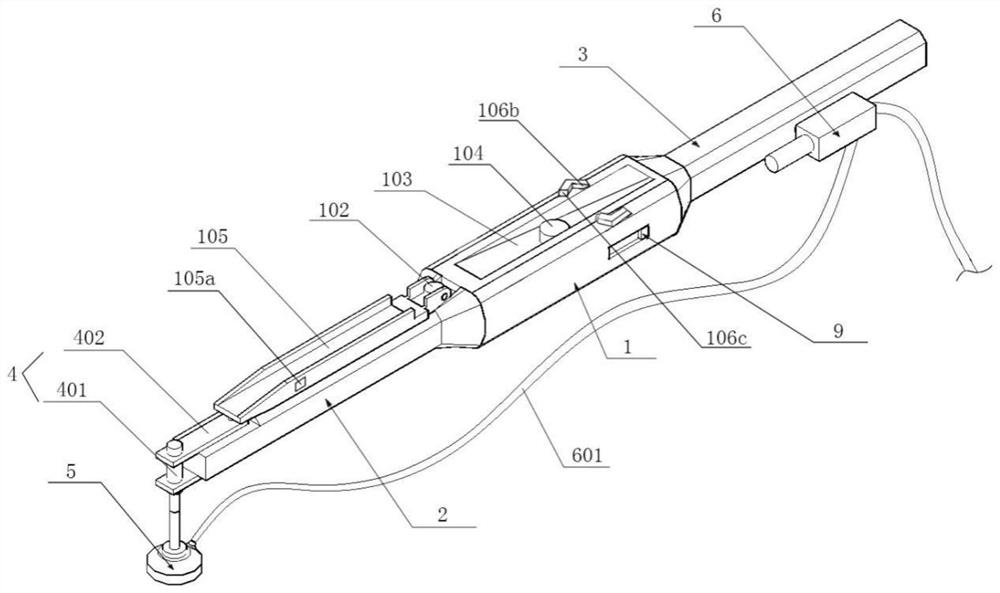
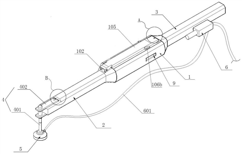
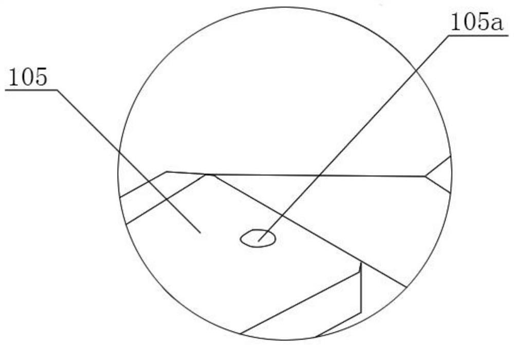
[0030] And definition: The two ends of the door-shaped elastic piece 106 are respectively defined as the first end 106a and the second end 106b.

[0031] Such as figure 1 with figure 2 As shown, a steel strip sample control device...


PUM


Abstract

The invention relates to a steel belt sample control device for sampling. The steel belt sample control device comprises a machine body which is internally provided with a hollow chamber, a front rodbody and a rear rod body which are formed on the front side and the rear side of the machine body, a gimbal which is rotationally disposed on the front rod body, an adsorption disc which is disposed on the gimbal, a vacuum generator which is disposed on the rear rod body, and a transmission assembly and a control assembly which are disposed in the chamber. A negative pressure pipe of the vacuum generator is connected with the adsorption disc. A rotary disc and a guide groove are disposed on the upper end face of the machine body. The end, close to the rear rod body, of the guide groove communicates with the chamber. A universal joint capable of rotating around a fixed point is disposed in the guide groove. A cover plate is rotationally disposed on the rotary disc. A limiting piece capableof clamping the cover plate is formed on the gimbal. The transmission assembly is connected with the rotary disc and the universal joint. The control assembly is connected with an input switch disposed on the machine body. By means of the technical scheme, there is no need to manually perform sampling directly, sampling can be performed at any angle and any position, and meanwhile no finished product waste can be caused.

Description

Technical field [0001] The invention relates to a sampling device, more specifically a steel strip sample control device for sampling. Background technique [0002] After the steel belt is laser cut in the machine, there will be two parts: the finished product and the waste. After the cutting is completed, the finished product and the waste will fall on the conveyor belt of the machine, and be transferred to the outside of the machine through the conveyor belt, and then the finished product and waste will be removed separately Differentiate and transport them to the finished product rack, so that the finished product can be quickly put into the next step of production. [0003] Sampling and testing of cut finished products is an indispensable link before putting it into production, and it is also one of the most critical links. At present, there are mainly two methods: direct manual sampling and sampling by mechanical arms. [0004] Among them, the manual sampling method requires th...

Claims


Application Information

Patent Timeline
IPC IPC(8): B23K26/70B65G15/00B65G47/91G01N1/04
CPCB65G15/00B65G47/91B23K26/702G01N1/04
Inventor 张栋
Owner 宁波宝钢不锈钢加工有限公司
Why Eureka
Eureka Blog
Learn More