Lower limb exoskeleton system with actively adjustable leg rod length and control method of lower limb exoskeleton system with actively adjustable leg rod length

A control method and exoskeleton technology, which can be applied to program-controlled manipulators, appliances that help people move, and manufacturing tools, etc., which can solve the problems of lack of prediction function, cost reduction, and weak limb sensory ability.

Active Publication Date: 2020-10-23
ZHEJIANG UNIV
View PDF13 Cites 8 Cited by
  • Summary
  • Abstract
  • Description
  • Claims
  • Application Information

AI Technical Summary

Problems solved by technology

[0005] By arranging the thigh bar and the calf bar in an adjustable length structure, the adaptation range of the lower extremity exoskeleton to the wearer's height can be effectively improved, and the cost can be effectively reduced; It is generally approximated as a hinge joint, and most exoskeleton designs approximate the flexion / extension of the hip joint and knee joint as a single-degree-of-freedom fixed-axis rotation hinge joint. The difference in the movement mechanism of the exoskeleton joints causes the relative movement between the human leg and the exoskeleton leg bar, and in the process of walking, there is a problem that the center position of the joint does not match. The positional deviation between them can reach the order of 10 mm. Because it is relatively small, it is ignored in the design of the existing exoskeleton because of the softness of human skin tissue. The binding between human legs is tight, and the small displacement difference will bring greater interference force. Long-term reciprocation will cause damage to the soft tissue of the lower limb joints, especially the limb sensory ability of patients with paralysis of the lower limbs. It is difficult to feel these negative effects, and there are large negative effects
[0006] In addition, when the exoskeleton system assists the wearer to move, the timing of driving the thigh bar to swing is judged based on the detection data of the pose detection sensor fixed on the thigh bar. Misjudgment of the impact of noise, resulting in uncoordinated movement between the walker and the human body
[0007] Aiming at the above-mentioned uncoordinated movement problem, the current solution is to collect the human muscle electrical signal and combine the adaptive oscillator algorithm to predict the quasi-periodic gait trajectory, so as to realize the precise assistance of the robot to the human hip joint; although this method can predict Eliminate the power-assist delay, but there are certain requirements for the periodicity of walking. When the wearer frequently changes the walking rhythm, the timing of the power-assist is disordered and affects coordination due to the inability to accurately predict it.
Or the phase angle oscillator can be used to accurately identify the corresponding gait phase of the human body in each walking cycle, so as to achieve accurate power-assisted control of the corresponding gait phase, but it can only be calculated in the current state after the joint angle is detected by the attitude sensor. The power assist value does not have a predictive function, and the power assist is still affected by the delay and there is a sense of lag

Method used


Image

  • Lower limb exoskeleton system with actively adjustable leg rod length and control method of lower limb exoskeleton system with actively adjustable leg rod length
  • Lower limb exoskeleton system with actively adjustable leg rod length and control method of lower limb exoskeleton system with actively adjustable leg rod length
  • Lower limb exoskeleton system with actively adjustable leg rod length and control method of lower limb exoskeleton system with actively adjustable leg rod length

Examples


Embodiment 1

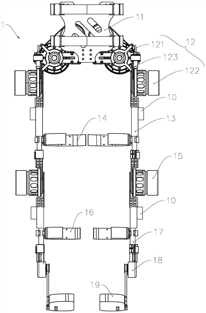
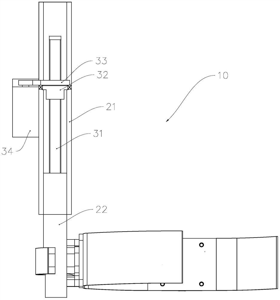
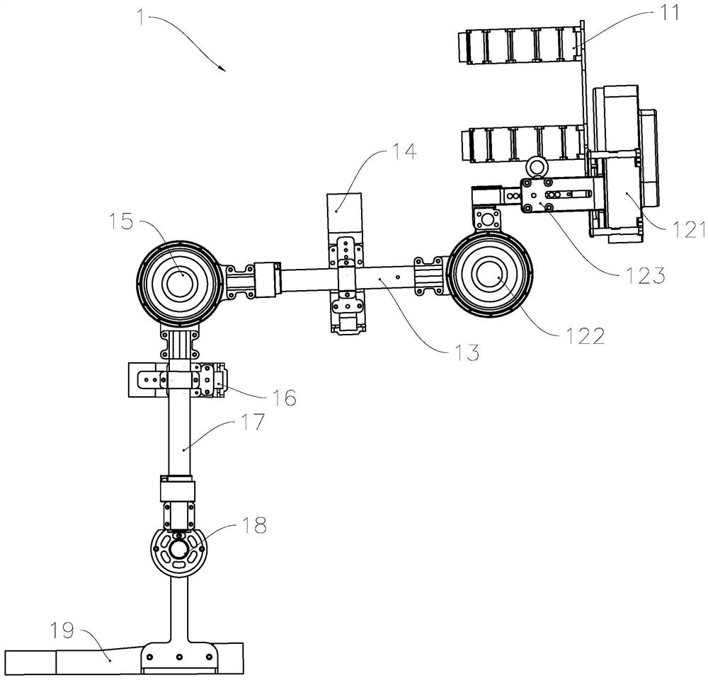
[0046] see Figure 1 to Figure 4 , The lower extremity exoskeleton system of the present invention includes a control unit, a detection unit and an exoskeleton 1 . The control unit includes a processor and a memory, and the detection unit outputs a detection signal to the control unit. In this embodiment, the detection unit includes an angle sensor for detecting the angle of each joint and a tension sensor placed on the strap for detecting the tension of the strap ; The control unit outputs control signals to the driving mechanisms of the exoskeleton to drive the exoskeleton to walk according to a predetermined trajectory.

[0047] The exoskeleton 1 includes a waist wearing unit 11 , a hip joint unit 12 , a thigh bar 13 , a thigh strap 14 , a knee joint unit 15 , a calf strap 16 , a calf bar 17 , an ankle unit 18 and a flexible sole unit 19 . The waist wearing unit 11 is used for fixing the exoskeleton system and the waist of the human body; the thigh bar 13 is used to drive ...

Embodiment 2

[0060] As a description of Embodiment 2 of the present invention, only the differences from Embodiment 1 above will be described below.

[0061] In this embodiment, the control method includes an acquisition step S21, a calculation step S22, and an adjustment step S23, and the specific process is as follows:

[0062] Obtaining step S21, acquiring joint angle data of the skeletal system of the lower limbs.

[0063] In the calculation step S22, according to a preset calculation model, the target leg lengths of the thigh bar unit and the calf bar unit are calculated based on the joint angle data.

[0064] In this step, based on the relationship between the existing leg length and joint angle, the calculation model is a cubic spline fitting calculation model represented by the following formula:

[0065]

[0066]

[0067] Among them, H hip (α) and H knee (β) are the target leg lengths of the exoskeleton thigh rod and calf rod, respectively, α and β are the hip joint and k...

Embodiment 3

[0070] As an explanation of Embodiment 3 of the present invention, only the differences from Embodiment 1 above will be described below.

[0071] In the control methods of the two above-mentioned embodiments, the thigh rod unit and the calf rod unit are controlled to adjust the parameters based on the parameter detection data that characterizes the lower extremity exoskeleton system being in motion, such as strap tension detection data and joint angle data. The length of the leg bar is to compensate for the position deviation between the joint rotation center position of the lower limb exoskeleton system and the wearer's lower limb joint rotation center position; and in this embodiment, during the use of the lower limb exoskeleton system, not only its legs The length of the rod is properly adjusted, and during the movement, based on the deformation of the walking rhythm, the swing state of the leg rod of the hip joint unit controller is controlled.

[0072] like Figure 5 As ...


PUM


Abstract

The invention relates to a lower limb exoskeleton system with actively adjustable leg rod length and a control method of the lower limb exoskeleton system with the actively adjustable leg rod length,and belongs to the technical field of wearable robots. The control method comprises the steps that according to parameter detection data representing that the lower limb exoskeleton system is in an action state, a thigh rod unit and a shank rod unit are controlled to adjust the leg rod lengths of the thigh rod unit and the shank rod unit until the position deviation between the joint rotation center position of the lower limb exoskeleton system and the lower limb joint rotation center position of a wearer is compensated. According to the control method of the lower limb exoskeleton system withthe actively adjustable leg rod length, the use safety is improved while the wearing comfort can be effectively improved, and the control method of the lower limb exoskeleton system with the activelyadjustable leg rod length can be widely applied to rehabilitation training of patients with lower limb weakness or hemiplegia or walking assistance of old people.

Description

technical field [0001] The invention relates to wearable robots and the field thereof, in particular to a lower extremity exoskeleton system with an actively adjustable leg rod length and a control method thereof. Background technique [0002] With the aging of the population, the number of stroke patients continues to increase; in addition, spinal cord injuries caused by traffic accidents, sports injuries and other injury factors are on the rise. Therefore, early rehabilitation training for patients is becoming more and more important. The more attention it receives, the mainstream is to use the plasticity of the central nervous system to make the affected side respond accordingly through exercise training, improve muscle tension, and establish a new combination of the nervous system. However, relying on the experience of physical therapists to perform manual rehabilitation training on patients is not only inefficient, but also unsatisfactory. The use of the lower extremit...

Claims


Application Information

Patent Timeline
Patent Type & Authority Applications(China)
IPC IPC(8): B25J9/00B25J9/16B25J17/02A61H3/00A61H1/02
CPCA61H1/0237A61H3/00A61H2003/005A61H2201/0192B25J9/0006B25J9/1656B25J17/0258
Inventor 杨巍徐铃辉曹斌彭桢哲杨灿军
Owner ZHEJIANG UNIV
Why Eureka
Try Eureka