Equipment and method for cutting vermiculite brick for building heat insulation
A technology for cutting equipment and vermiculite bricks, which is applied to stone processing equipment, stone processing tools, work accessories, etc., and can solve the problems of manual movement and easy deviation
- Summary
- Abstract
- Description
- Claims
- Application Information
AI Technical Summary
Problems solved by technology
Method used
Image
Examples
Embodiment 1
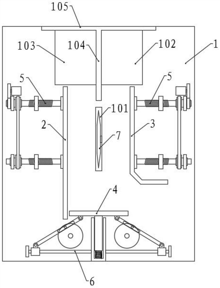
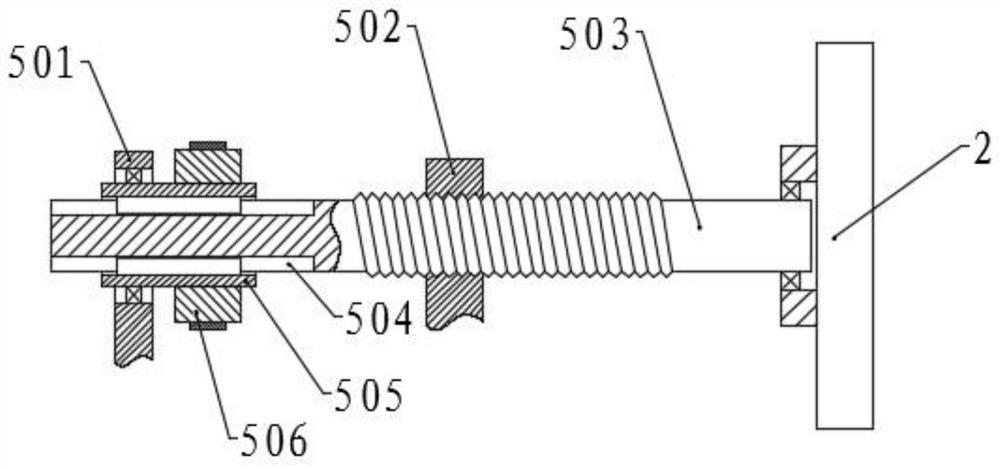
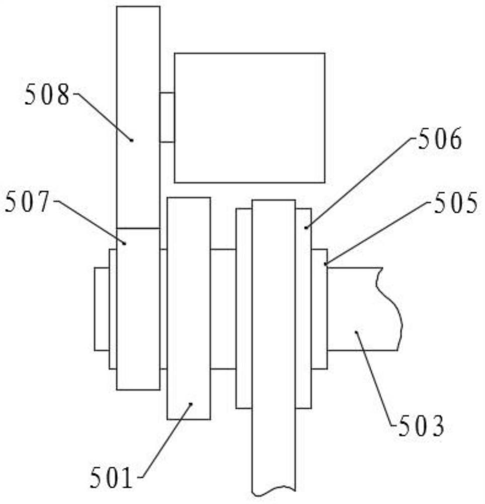
[0051] Please refer to the accompanying drawings, the present invention provides a technical solution: a vermiculite brick cutting equipment for building heat insulation, including a base, the top surface of the base is fixed with a workbench 1 through a support rod, and the middle of the top surface of the workbench 1 Cutting groove 101 is provided, and cutting assembly 7 is arranged at cutting groove 101, and the left side of cutting groove 101 is provided with first positioning plate 2, and the right side is provided with second positioning plate 3, and first positioning plate 2 is longer than second positioning plate 3, and the outer sides of the first positioning plate 2 and the second positioning plate 3 are respectively connected with two positioning components, the top front side of the workbench 1 is provided with a push plate 4, and a slide bar 401 is fixed in the middle of the front side of the push plate 4, Both sides are symmetrically provided with a push assembly ...
Embodiment 2
[0063] The structure of this embodiment is basically the same as that of Embodiment 1, the difference is that a sealing plate 10 is provided at the middle and top of the first feeding port 102 and the second feeding port 103, and a vertical board 1001 is provided at the middle and lower part of the sealing board 10 , and one side of the vertical plate 1001 is the second chute 108, and the other side is provided with a conveying assembly, the sealing plate 10 is connected to the top of the vertical plate 1001 in rotation, and a motor is provided at the rotating connection, and the sealing plate 10 is driven by the motor. Rotate the rod 603, the conveying assembly includes two side plates 1004 symmetrically fixed on the vertical plate 1001, the inner section and the outer section of the side plate 1004 are respectively connected with the conveying roller 1002, and the two conveying rollers 1002 are provided with the conveying belt 1003 , and one of the conveying rollers 1002 is c...
Embodiment 3
[0066] The structure of this embodiment is basically the same as that of Embodiment 2, the difference being that a pulverizing assembly is provided in the second feeding chute 108, and the bottom end of the dividing plate 104 extends into the second feeding chute 108, and the second feeding chute In 108, two rotating shafts 901 are symmetrically and parallelly arranged, and the two ends and the middle part of the rotating shaft 901 are respectively connected with the two side walls of the second feeding chute 108 and the partition 104 in rotation, and two rotating shafts are fixed on the same second rotating shaft. One pulverizing roller 9, and is respectively positioned at the both sides of dividing plate 104, is correspondingly connected with two pulverizing rollers 9 on another rotating shaft 901, and the upper part of the second unloading chute 108 corresponds to the pulverizing roller 9 on both sides of dividing plate 104. The position is provided with a collecting plate, ...
PUM
 Abstract
Description
Claims
Application Information
 - R&D
- Intellectual Property
- Life Sciences
- Materials
- Tech Scout
- Unparalleled Data Quality
- Higher Quality Content
- 60% Fewer Hallucinations
Browse by: Latest US Patents, China's latest patents, Technical Efficacy Thesaurus, Application Domain, Technology Topic, Popular Technical Reports.
© 2025 PatSnap. All rights reserved.Legal|Privacy policy|Modern Slavery Act Transparency Statement|Sitemap|About US| Contact US: help@patsnap.com


