
Battery liquid cooling system and filling method of anti-freezing solution of battery liquid cooling system

A cooling system and battery fluid technology, applied in the field of electric vehicles, can solve problems such as affecting the off-line efficiency of the whole vehicle, low efficiency, and affecting the filling efficiency.

Pending Publication Date: 2020-10-23
青岛朗进新能源设备有限公司
View PDF0 Cites 2 Cited by
  • Summary
  • Abstract
  • Description
  • Claims
  • Application Information

AI Technical Summary

Problems solved by technology

[0002] At present, more and more pure electric buses use air-conditioning liquid cooling instead of traditional air-cooling to dissipate heat for the battery. By cooling the battery, the loss rate of the battery can be reduced and the service life of the battery can be improved. Most of the battery air-conditioning water tanks are arranged on the roof. When adding antifreeze to the waterway system for the first time, it needs to be manually filled on the roof. Due to the long waterway, large water resistance, and slow automatic exhaust efficiency, there is a large amount of gas in the waterway, which affects the filling efficiency and usually leads to full filling. The antifreeze of a car needs to be filled continuously for 2 hours, and the efficiency is too low, which will affect the efficiency of the whole vehicle off the assembly line

Method used


Image

  • Battery liquid cooling system and filling method of anti-freezing solution of battery liquid cooling system
  • Battery liquid cooling system and filling method of anti-freezing solution of battery liquid cooling system
  • Battery liquid cooling system and filling method of anti-freezing solution of battery liquid cooling system

Examples


Embodiment

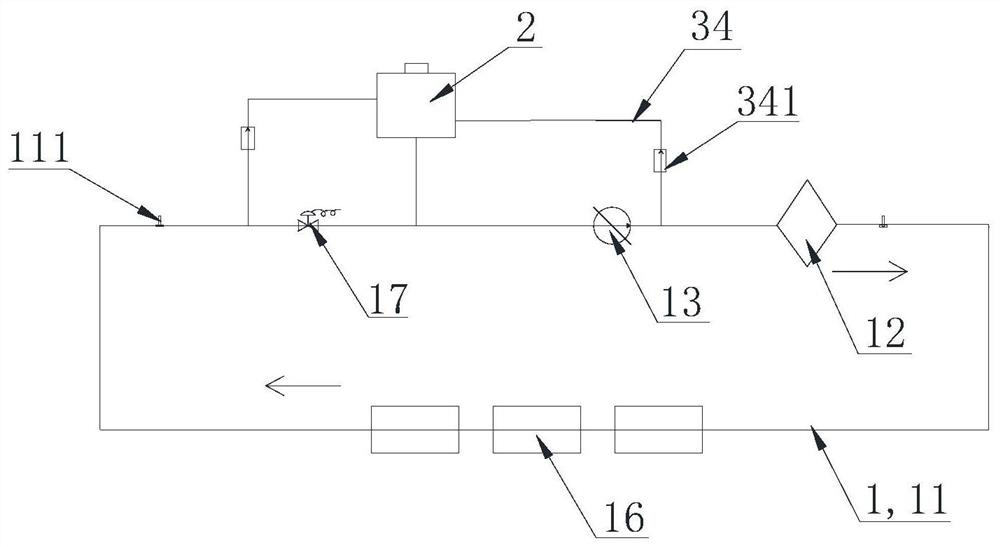
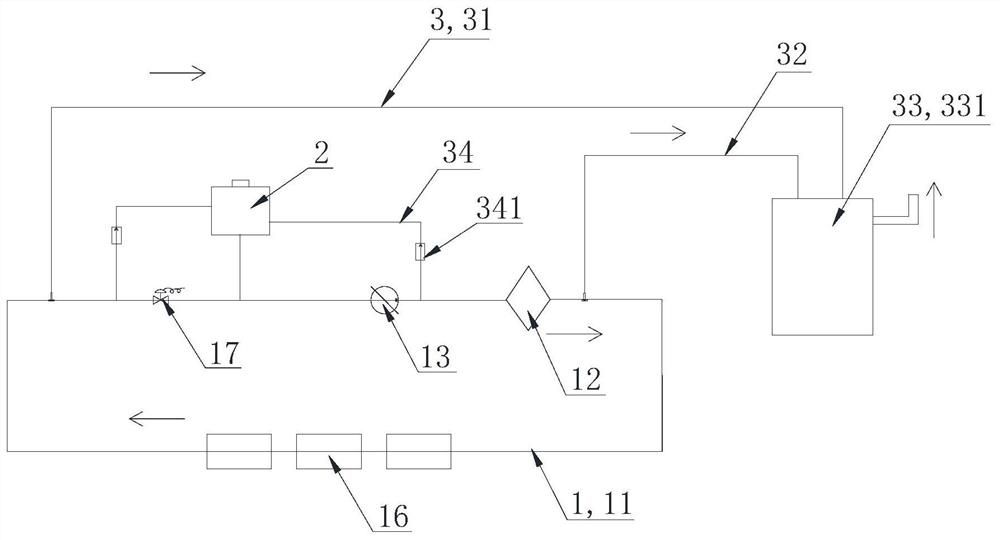
[0031] like figure 1 and figure 2 As shown, the present invention provides a battery liquid cooling system, including a cooling unit 1, an antifreeze filling tank 2 and at least one exhaust pipe 3, the cooling unit 1 includes a circulation pipeline 11 and a water pump 13, and the antifreeze filling tank 2 The liquid chamber and the water pump 13 are sequentially connected in series on the circulation pipeline 11 along the circulation direction of the fluid. A first control valve is connected in series.

[0032] In the embodiment of the present invention, for the battery liquid cooling system, the liquid cavity of the antifreeze filling tank 2 is filled with antifreeze into the circulation pipeline 11 through the pipeline, and the antifreeze filling tank 2 is used to add antifreeze to the circulation pipeline 11. Before injecting antifreeze, close the first control valve 17, connect the exhaust pipe 3 to discharge the gas left in the circulation pipeline 11 to the outside, a...


PUM


Abstract

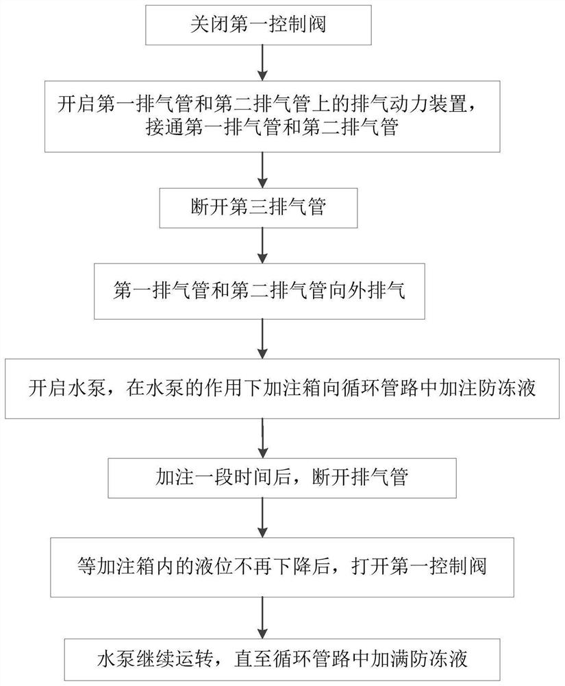
The invention discloses a battery liquid cooling system and a filling method of an anti-freezing solution of a battery liquid cooling system. The battery liquid cooling system comprises a cooling unit, an anti-freezing solution filling box and at least one exhaust pipe, the cooling unit comprises a circulating pipeline and a water pump, a liquid cavity of the anti-freezing solution filling box andthe water pump are sequentially connected to the circulating pipeline in series in the circulating direction of fluid, the air inlet of each exhaust pipe is communicated with the circulating pipeline, and a first control valve is connected to the circulating pipeline located in the upstream of the anti-freezing solution filling box in series. The first control valve is connected to the circulating pipeline in the upstream of the anti-freezing solution filling box in series, so that the anti-freezing solution filling efficiency is improved. According to the filling method of the battery liquidcooling system anti-freezing solution, the first control valve is closed; the exhaust pipe is connected, the exhaust pipe exhausts air outwards, the water pump is started, the anti-freezing solutionfilling box fills the anti-freezing solution into the circulating pipeline under the effect of the water pump, after filling is conducted for a period of time, the exhaust pipe is disconnected, and after the liquid level in the anti-freezing solution filling box does not drop any more, the first control valve is opened to complete filling of the anti-freezing solution.

Description

technical field [0001] The invention belongs to the field of electric vehicles, and in particular relates to a battery liquid cooling system and a method for filling antifreeze in the battery liquid cooling system. Background technique [0002] At present, more and more pure electric buses use air-conditioning liquid cooling instead of traditional air-cooling to dissipate heat for the battery. By cooling the battery, the loss rate of the battery can be reduced and the service life of the battery can be improved. Most of the battery air-conditioning water tanks are arranged on the roof. When adding antifreeze to the waterway system for the first time, it needs to be manually filled on the roof. Due to the long waterway, large water resistance, and slow automatic exhaust efficiency, there is a large amount of gas in the waterway, which affects the filling efficiency and usually leads to full filling. The antifreeze of a car needs to be filled continuously for 2 hours, and the ...

Claims


Application Information

Patent Timeline
Patent Type & Authority Applications(China)
IPC IPC(8): B60H1/00B60H1/32B60L58/26
CPCB60H1/00278B60H1/00371B60H1/00392B60H1/00485B60H1/00592B60H1/0065B60H1/00792B60H1/32B60H2001/00614B60L58/26Y02T10/70
Inventor 李敬恩史长奎高福学管庆禹
Owner 青岛朗进新能源设备有限公司
Learn More