
C-ring structure of new energy automobile

A new energy vehicle, left and right technology, applied to the upper structure, upper structure sub-assembly, vehicle parts, etc., can solve the problem of car body damage

Active Publication Date: 2020-10-23
ZHEJIANG LEAPMOTOR TECH CO LTD
View PDF9 Cites 3 Cited by
  • Summary
  • Abstract
  • Description
  • Claims
  • Application Information

AI Technical Summary

Problems solved by technology

However, this patented technical solution is not suitable for solving the problem of damage to the body caused by the strong impact load brought by the rear axle load of some new energy vehicles.

Method used


Image

  • C-ring structure of new energy automobile
  • C-ring structure of new energy automobile
  • C-ring structure of new energy automobile

Examples


Embodiment Construction

[0019] The technical solutions of the present invention will be further specifically described below through the embodiments and in conjunction with the accompanying drawings.

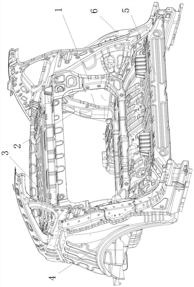
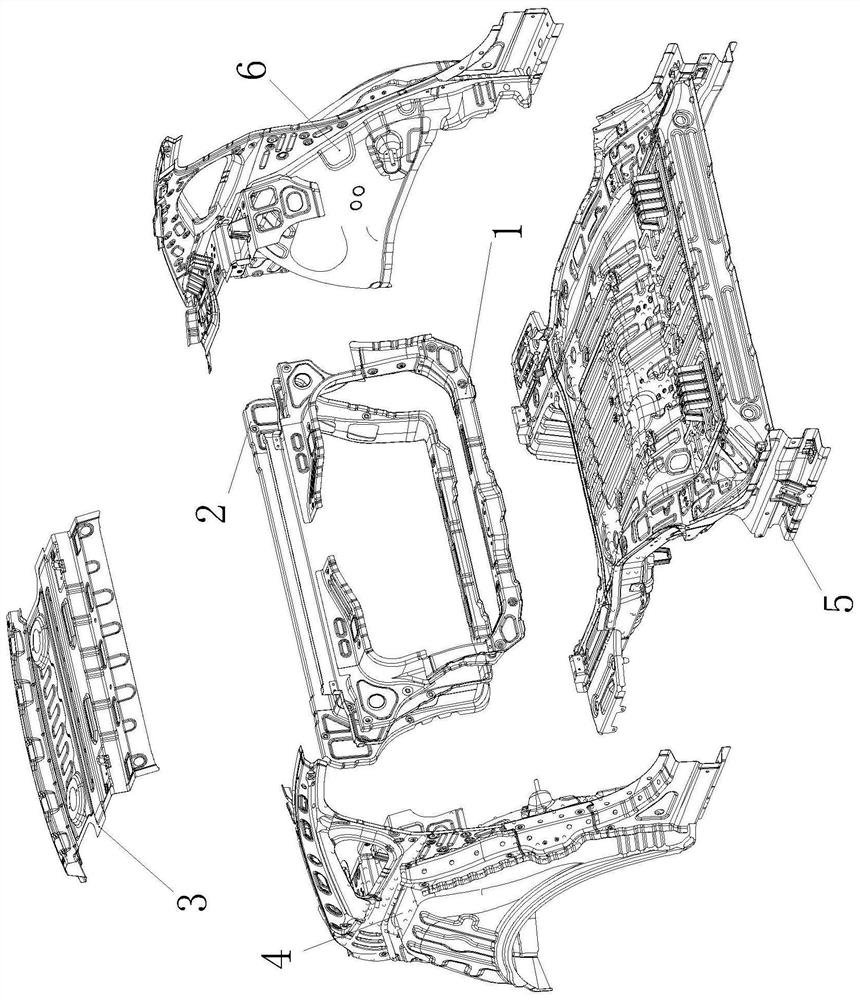
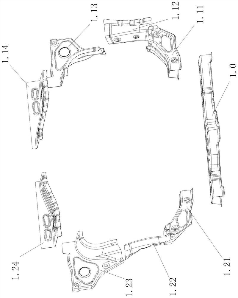
[0020] Such as figure 1 , figure 2 , image 3 , Figure 4 As shown, the present invention includes a front C-ring assembly 1 and a rear C-ring assembly 2;

[0021] Front C-ring assembly 1 includes front and rear floor upper crossbeam assembly 1.0, left front and rear floor upper crossbeam plate 1.11, right front and rear floor upper crossbeam plate 1.21, left wheelhouse front lower plate 1.12, right wheelhouse front lower plate 1.22, left and right wheelhouse front Plate 1.13, right wheelhouse front plate 1.23, left rear storage platform front beam 1.14, right rear storage platform front beam 1.24; the left and right ends of the front and rear floor upper beam assembly 1.0 are respectively connected with the left front and rear floor upper beam plate 1.11 and the right front and rear floor The low...


PUM


Abstract

A C-ring structure of a new energy automobile is formed by connecting a front C-ring assembly, a rear C-ring assembly, a rear storage table assembly, a right rear wheel cover assembly, a rear floor assembly and a left rear wheel cover assembly. The front C-ring assembly is formed by connecting a front and rear floor upper cross beam assembly, a left front and rear floor upper cross beam plate, a right front and rear floor upper cross beam plate, a left wheel cover front lower plate, a right wheel cover front lower plate, a left wheel cover front plate, a right wheel cover front plate, a left rear storage table front cross beam and a right rear storage table front cross beam; and the rear C-ring assembly is formed by connecting a rear floor rear upper cross beam assembly, a left rear floorupper rear cross beam plate, a right rear floor upper rear cross beam plate, a left wheel cover rear plate, a right wheel cover rear plate and a rear storage table rear cross beam. A complete force conduction path can be constructed on one side of a shock absorber, torsional rigidity and strength of a rear side wall assembly are greatly improved, and the C-ring structure is stable in structure, light in weight and beneficial to reducing energy consumption of a new energy automobile and increasing anendurance mileage of the new energy automobile.

Description

technical field [0001] The invention relates to a C-ring structure of a new energy vehicle. Background technique [0002] For some models of new energy vehicles, due to the arrangement of power batteries, the load on the rear axle of the car is large, and the impact load of the rear shock absorber on the wheel cover area of ​​the car is greater than that of traditional models. Under the impact of large loads, in order to ensure driving safety, there are high requirements on the strength of the rear side panel assembly and the wheel cover. A good force transmission structure and a complete C-ring structure can improve the torsional stiffness and modulus of the body-in-white. state, thereby solving the damage to the body caused by the strong impact load and improving the stability of the vehicle operation. [0003] Application number 201310743112.1, authorized announcement number CN 103693115 B, Chinese invention patent titled "automobile rear wheel house inner panel reinforc...

Claims


Application Information

Patent Timeline
IPC IPC(8): B62D25/20B62D25/16B62D25/18B62D25/08
CPCB62D25/08B62D25/16B62D25/18B62D25/20
Inventor 凌勇刘建胜郭大洲肖淘
Owner ZHEJIANG LEAPMOTOR TECH CO LTD
Learn More