Straw mat winding machine for batch production of straw mats
A batch and winding machine technology, which is applied in the directions of winding strips, thin material handling, transportation and packaging, etc., can solve the problems of uneven straw mats, labor-intensive, and straw mat wrinkles
- Summary
- Abstract
- Description
- Claims
- Application Information
AI Technical Summary
Problems solved by technology
Method used
Image

Examples
Embodiment 1
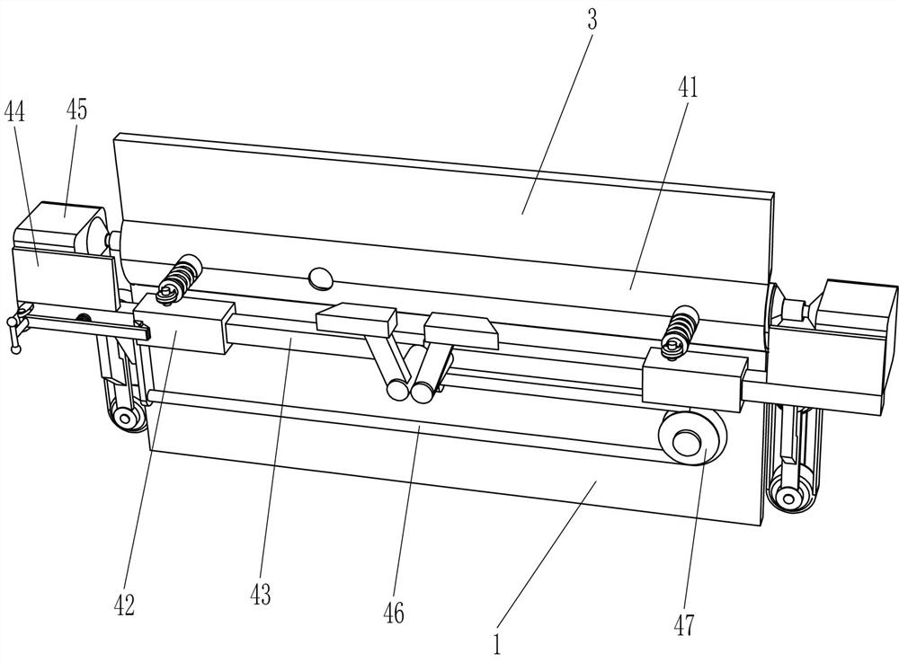
[0030] A kind of straw mat batch production with straw mat winding machine, such as Figure 1-6 As shown, it includes a bracket 1, a slant plate 2 and a baffle 3, the slant plate 2 is connected to the top of the bracket 1, the baffle 3 is connected to the right side of the slant plate 2, and a winding mechanism 4 and a clamping mechanism 5 are also included. The plate 2 is provided with a winding mechanism 4, and the winding mechanism 4 is provided with a clamping mechanism 5.
[0031] Rewinding mechanism 4 includes arc plate 41, sliding sleeve 42, slide bar 43, mounting plate 44, geared motor 45, stay cord 46, guide wheel 47, damping rod 48, damping tube 49 and slotted tube 410, swash plate 2 The right side is embedded with an arc-shaped plate 41, and the right side of the bottom of the inclined plate 2 is connected with two sliding sleeves 42. The side that bar 43 is far away from each other is all connected with mounting plate 44, and geared motor 45 is installed on the mo...
Embodiment 2
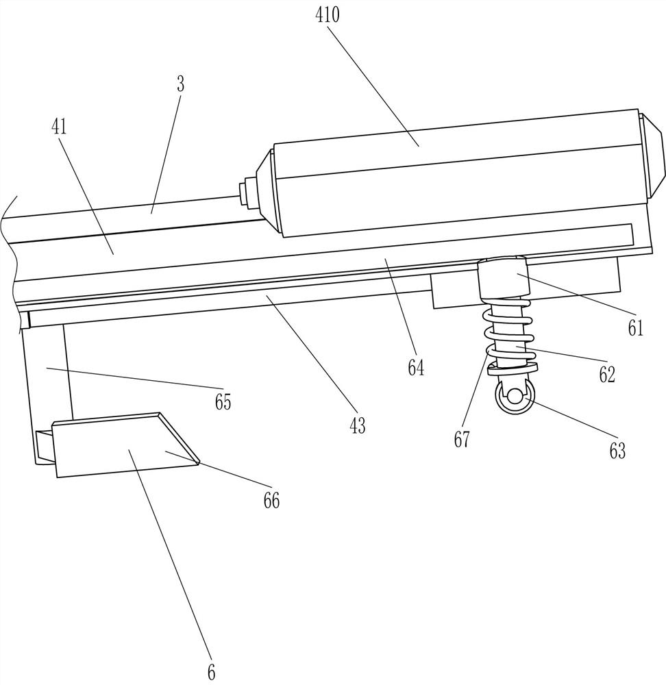
[0035] On the basis of Example 1, such as Figure 7As shown, push-up mechanism 6 is also included, and push-up mechanism 6 includes guide sleeve 61, guide rod 62, contact wheel 63, push plate 64, connecting rod 65, wedge block 66 and second spring 67, arc plate 41 Both the front and rear parts are embedded with guide sleeves 61, the guide sleeves 61 are slidingly connected with guide rods 62, the bottom of the guide rods 62 is rotatably connected with contact wheels 63, and the tops of the two guide rods 62 are connected with push plates 64. Push plate 64 is positioned at arc-shaped plate 41 tops, and the slide bar 43 bottom inner side of front and back both sides is all connected with connecting rod 65, and connecting rod 65 bottoms are connected with wedge-shaped block 66, and wedge-shaped block 66 cooperates with contact wheel 63, and guide rod 62 and guide rod 65 are connected with each other. A second spring 67 is connected between the sleeves 61 .
[0036] The unclamped...
Embodiment 3
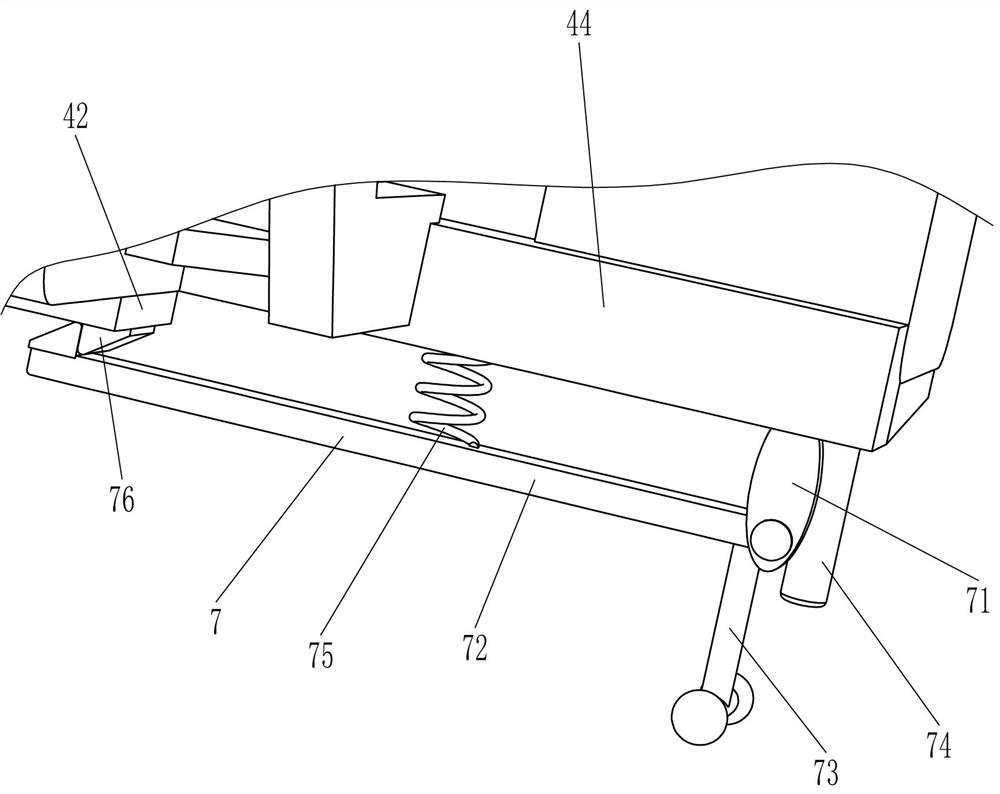
[0038] On the basis of Example 2, such as Figure 8 As shown, a locking mechanism 7 is also included, and the locking mechanism 7 includes a hinged plate 71, a hook 72, a pull rod 73, a limit rod 74, a third spring 75 and a block 76, and the bottom of the front mounting plate 44 is connected with a hinged plate 71 , the hinge plate 71 is hingedly connected with a hook 72, the front side of the hook 72 is connected with a pull rod 73, and the front side of the bottom of the front mounting plate 44 is connected with a limit rod 74, and the limit rod 74 cooperates with the pull rod 73, and the connection between the hook 72 and the mounting plate 44 A third spring 75 is connected between them, and a block 76 is connected to the bottom of the front sliding sleeve 42, and the block 76 cooperates with the hook 72.
[0039] When the straw mat is rolled up, the hook 72 cooperates with the block 76 to lock the mounting plate 44, avoiding the displacement of the mounting plate 44. After...
PUM
 Abstract
Description
Claims
Application Information
 - R&D
- Intellectual Property
- Life Sciences
- Materials
- Tech Scout
- Unparalleled Data Quality
- Higher Quality Content
- 60% Fewer Hallucinations
Browse by: Latest US Patents, China's latest patents, Technical Efficacy Thesaurus, Application Domain, Technology Topic, Popular Technical Reports.
© 2025 PatSnap. All rights reserved.Legal|Privacy policy|Modern Slavery Act Transparency Statement|Sitemap|About US| Contact US: help@patsnap.com