Laser cladding device and laser cladding method for long and thin workpiece

A laser cladding, slender technology, applied in the direction of metal material coating process, coating, etc., can solve the problems of large temperature difference of workpiece, personal injury of personnel, and large difference of product quality, etc.

Active Publication Date: 2020-10-23
江苏智远激光装备科技有限公司
View PDF5 Cites 3 Cited by
  • Summary
  • Abstract
  • Description
  • Claims
  • Application Information

AI Technical Summary

Problems solved by technology

[0003] The workpiece needs to be preheated before laser cladding, and the quality of the preheating effect determines the quality after processing to a certain extent; in the prior art, the workpiece is preheated first, and then using fixtures, laser cladding The cladding on the surface of the workpiece is completed with the use of the head; there are the following disadvantages in the operation of this method. First, when the workpiece is clamped after preheating, it may cause personal injury to personnel due to high temperature; second, after preheating After the workpiece is clamped, due to the influence of the external temperature, the temperature difference of the workpiece during laser cladding treatment is relatively large, resulting in a large difference in product quality of the same batch of products

Method used


Image

  • Laser cladding device and laser cladding method for long and thin workpiece
  • Laser cladding device and laser cladding method for long and thin workpiece
  • Laser cladding device and laser cladding method for long and thin workpiece

Examples


Embodiment Construction

[0039] The following will clearly and completely describe the technical solutions in the embodiments of the present invention with reference to the accompanying drawings in the embodiments of the present invention. Obviously, the described embodiments are only some, not all, embodiments of the present invention. Based on the embodiments of the present invention, all other embodiments obtained by persons of ordinary skill in the art without making creative efforts belong to the protection scope of the present invention. In addition, all the connection relationships mentioned in this article do not refer to the direct connection of components, but mean that a better connection structure can be formed by adding or reducing connection accessories according to the specific implementation situation.

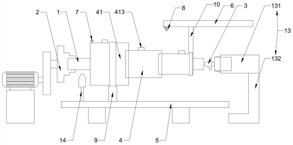
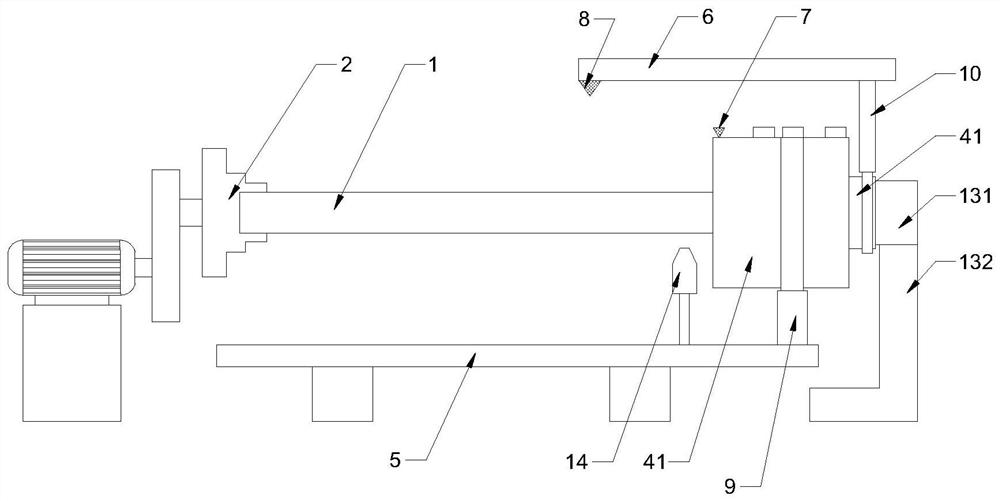
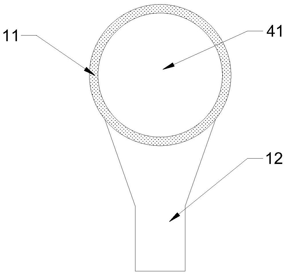
[0040] see Figure 1-7As shown, a laser cladding device for a slender workpiece includes a gripper 2, a thimble 3, a telescopic preheating sleeve 4, a laser cladding nozzle 14, a first...


PUM


Abstract

The invention discloses a laser cladding device and a laser cladding method for a long and thin workpiece. The laser cladding device comprises a clamping jaw, an ejector pin, a telescopic preheating sleeve, a laser cladding nozzle, a first guide rail and a second guide rail, wherein the clamping jaw and the ejector pin clamp the two ends of the workpiece; the laser cladding nozzle slides on the first guide rail; the telescopic preheating sleeve comprises a plurality of sections of heating cylinders of which the diameters are sequentially reduced from the clamping jaw to the ejector pin; the heating cylinder with the maximum diameter is connected to the first guide rail through a first bracket in a sliding manner; the heating cylinder with the minimum diameter is connected to the second guide rail through a second bracket in a sliding manner; the telescopic preheating sleeve synchronously moves and contracts along with the movement of the laser cladding nozzle, so that the workpiece isalways kept in a preheating state before laser cladding; after the laser cladding of the workpiece is finished, the telescopic preheating sleeve reversely moves and stretches, so that the workpiece issubjected to heat treatment; the workpiece is clamped and then preheated, so that the safety of a worker in the operation process is protected; and the workpiece is preheated and subjected to heat treatment, so that the residual stress of a cladding layer can be effectively controlled, the crack damage is reduced, and the laser cladding quality is improved.

Description

technical field [0001] The invention relates to the technical field of laser cladding, in particular to a laser cladding device and a laser cladding method for a slender workpiece. Background technique [0002] Laser cladding technology refers to placing selected coating materials on the surface of the coated substrate with different filler methods, melting it and a thin layer of the substrate surface at the same time through laser irradiation, and forming a very low dilution and coating material after rapid solidification. A surface coating that forms a metallurgical combination with the base material, thereby significantly improving the wear resistance, corrosion resistance, heat resistance, oxidation resistance, and electrical properties of the base material surface. [0003] The workpiece needs to be preheated before laser cladding, and the quality of the preheating effect determines the quality after processing to a certain extent; in the prior art, the workpiece is pre...

Claims


Application Information

Patent Timeline
IPC IPC(8): C23C24/10
CPCC23C24/10
Inventor 林学春农光壹林培晨杭骏祥
Owner 江苏智远激光装备科技有限公司
Why Eureka
Try Eureka