

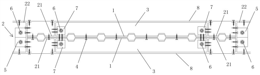
A cold-formed steel embedded double corrugated steel plate shear wall
A steel plate shear wall and corrugated steel plate technology, applied in the direction of walls, earthquake resistance, building components, etc., can solve the problems of affecting bearing capacity, buckling instability, loud noise, etc., achieve good integrity and continuity, and improve shear strength , the effect of high buckling capacity
- Summary
- Abstract
- Description
- Claims
- Application Information
AI Technical Summary
Problems solved by technology
Method used
Image

Examples
Embodiment Construction
[0048] In order to facilitate the understanding of the present invention, the present invention will be described more fully and in detail below in conjunction with the accompanying drawings and preferred embodiments, but the protection scope of the present invention is not limited to the following specific embodiments. It should be noted that, in the case of no conflict, the embodiments of the present invention and the features in the embodiments can be combined with each other.
[0049] Unless otherwise defined, all technical terms used hereinafter have the same meanings as commonly understood by those skilled in the art. "First", "second" and similar words used in the patent application specification and claims of the present invention do not indicate any order, quantity or importance, but are only for the convenience of distinguishing corresponding components. Likewise, words like "a" or "one" do not indicate a limitation of quantity, but indicate that there is at least on...
PUM
| Property | Measurement | Unit |
|---|---|---|
| thickness | aaaaa | aaaaa |
Abstract
Description
Claims
Application Information