Design method of adjustable nozzle blade of megawatt radial turbine expander

A technology of turboexpander and nozzle blades, which is applied in mechanical equipment, engine components, machines/engines, etc., and can solve problems such as nozzle blade design, impeller high-cycle fatigue, and nozzle outlet airflow unevenness

Pending Publication Date: 2020-10-23
HARBIN ELECTRIC POWER GENERATION EQUIP NAT ENG RES CENT CO LTD
View PDF6 Cites 0 Cited by
  • Summary
  • Abstract
  • Description
  • Claims
  • Application Information

AI Technical Summary

Problems solved by technology

[0005] The invention provides a method for designing adjustable nozzle blades of a megawatt-level radial turboexpander. week fatigue problem

Method used


Image

  • Design method of adjustable nozzle blade of megawatt radial turbine expander
  • Design method of adjustable nozzle blade of megawatt radial turbine expander
  • Design method of adjustable nozzle blade of megawatt radial turbine expander

Examples


specific Embodiment approach 1

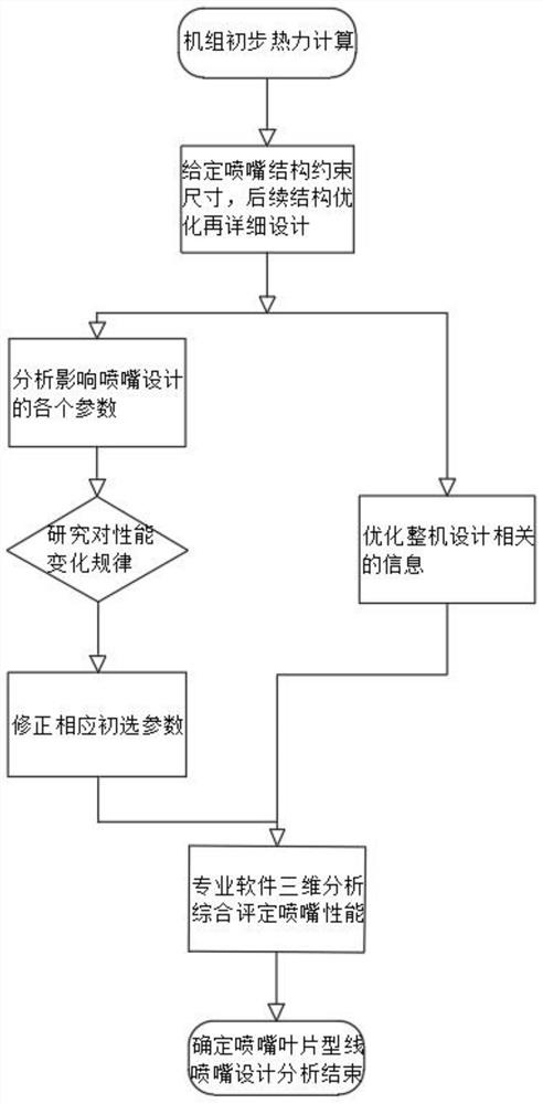
[0043] Specific implementation mode one: combine Figure 1-Figure 10 Describe this embodiment, the design method of the adjustable nozzle vane of a kind of megawatt class radial turbo expander of this embodiment, comprises the following steps:

[0044] Step 1: Determine the parameters of the preliminary nozzle. In the one-dimensional design, the nozzle design usually adopts empirical design. The main reason is that in the three-dimensional geometric modeling, the chord length and angle distribution of the nozzle blade will directly affect its radial length distribution. For impeller design, usually due to mutual constraints in structural design, the size of the nozzle will be adjusted for preliminary design, and the parameters of the nozzle will be initially fixed. The chord length of the nozzle blade 2 / the pitch of the nozzle outlet is b / l 1n =1.8, Nozzle blade 2 number Z N =21, as shown in Table 1;

[0045] Table 1 Comparison table of main parameters of aerodynamic structu...

specific Embodiment approach 2

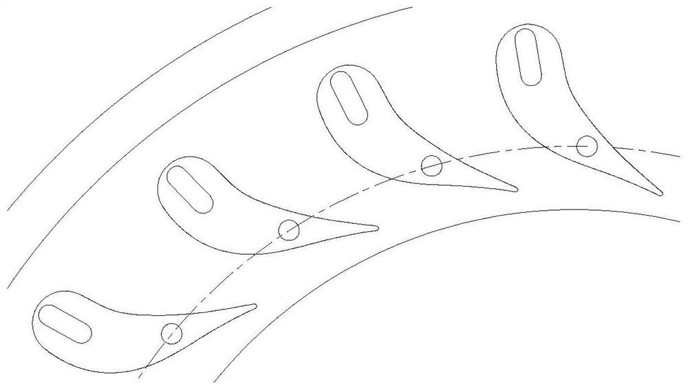
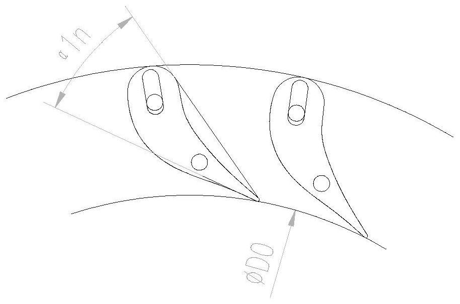
[0061] Specific implementation mode two: combination Figure 7 Describe this embodiment, a device and method for obtaining the best imaging parameters of the bearing cylindrical roller cylinder in this embodiment, complete the following three-dimensional design in professional design software, based on the relevant design criteria of the nozzle, select the nozzle blade 2 In the airfoil selection, focus on large-thickness inlet and better aerodynamic performance, combined with market research, and the design requirements of the main engine mechanism, this plan uses a certain airfoil as the basis for nozzle airfoil design, and the inlet section of nozzle blade 2 is R15. 77, which is advantageous from an aerodynamic point of view.

specific Embodiment approach 3

[0062] Specific implementation mode three: combination Figure 4-Figure 5 This embodiment is described, which is a design method for adjustable nozzle blades of a megawatt radial turboexpander. After the nozzle blade type is selected, the rationality of its flow field directly determines the impact on the performance of the whole machine. Focus on two points in the flow field analysis: ① The separation of the flow field should be as small as possible; ② The acceleration state should be ensured in the cascade channel; Except for the small flow separation loss and wake loss in the outlet section of the suction surface, there is no other loss in the entire flow field; from the absolute Mach number distribution cloud diagram of the flow field, we can see that in the cascade channel, the velocity distribution level is obvious, The flow in the entire channel presents a state of obvious acceleration, and there is no channel expansion; therefore, from the above analysis, it can be see...


PUM


Abstract

The invention relates to a design method of an adjustable nozzle blade of an expander, and belongs to the field of radial turbine. The design method aims to solve the problem of high cycle fatigue caused by direct impact on an impeller due to nonuniformity of airflow of a nozzle outlet because the nozzle blade is not designed in the prior art. The design method comprises the following steps of giving the limited size of a nozzle mechanism, analyzing all parameters which influence the nozzle design, researching the law of change in performance, correcting the corresponding primary parameter andcomprehensively evaluating the nozzle performance through three-dimensional analysis of professional software. The unique design method for correcting the blade is created, so that the airflow of thenozzle outlet is uniform, and the impact on the impeller is reduced.

Description

technical field [0001] The invention relates to a design method of adjustable nozzle vanes, belonging to the field of radial turbines. Background technique [0002] In the turboexpander, the main components that affect the efficiency are the nozzle blades and the expander impeller. Among them, the nozzle has the greatest influence. If the nozzle velocity coefficient is increased by one percentage point, the efficiency of the entire expander is also increased by almost one percentage point. The turbo expander The way to adjust the flow rate is to adopt the adjustable nozzle structure, and the smoothness of the profile line of the nozzle blade determines the smoothness of the air inlet. [0003] The nozzle ring is composed of several guide vanes, and each vane is arranged at the impeller inlet at equal intervals. The pressure of the airflow passing through the nozzle passage decreases, and the flow velocity gradually increases. The airflow at the outlet of the nozzle is very ...

Claims


Application Information

Patent Timeline
Patent Type & Authority Applications(China)
IPC IPC(8): F01D9/04F01D17/16
CPCF01D9/041F01D17/165
Inventor 王丽红郭祖光刘勇邵志伟孙涛苑馨予冯永志冀文慧王颖单维佶丁继伟
Owner HARBIN ELECTRIC POWER GENERATION EQUIP NAT ENG RES CENT CO LTD
Why Eureka
Try Eureka