
Double-end-face dry gas sealing device for industrial steam turbine

An industrial steam turbine and dry gas sealing technology, which is applied to mechanical equipment, engine components, machines/engines, etc., can solve problems such as large cooling water consumption, steam energy loss, and complicated situations

Pending Publication Date: 2020-10-23
徐冉
View PDF0 Cites 2 Cited by
  • Summary
  • Abstract
  • Description
  • Claims
  • Application Information

AI Technical Summary

Problems solved by technology

The leakage of steam will cause energy loss. In addition, the leaked steam needs to be cooled by cooling water, and the amount of cooling water is also very large.
According to statistics, for a medium-sized steam turbine unit, the annual steam leakage, cooling water consumption, and subsequent operation and maintenance costs are equivalent to an operating cost of more than one million yuan
[0005] Different from the dynamic and static seals of general machinery, there are many factors affecting the shaft end seal of industrial steam turbines, and the situation is complicated

Method used


Image

  • Double-end-face dry gas sealing device for industrial steam turbine
  • Double-end-face dry gas sealing device for industrial steam turbine
  • Double-end-face dry gas sealing device for industrial steam turbine

Examples


Embodiment Construction

[0028] Preferred embodiments of the present invention are described below with reference to the accompanying drawings. Those skilled in the art should understand that these embodiments are only used to explain the technical principles of the present invention, and are not intended to limit the protection scope of the present invention.

[0029] It should be noted that, in the description of the present invention, terms such as “inside” and “outside” indicating direction or positional relationship are based on the relative indication direction or positional relationship centered on the main body of the industrial steam turbine, which is only for the convenience of description, It is not intended to indicate or imply that the device or element must have a particular orientation, be constructed in a particular orientation, or operate in a particular orientation, and thus should not be construed as limiting the invention.

[0030] A double-end dry gas seal device for industrial st...


PUM


Abstract

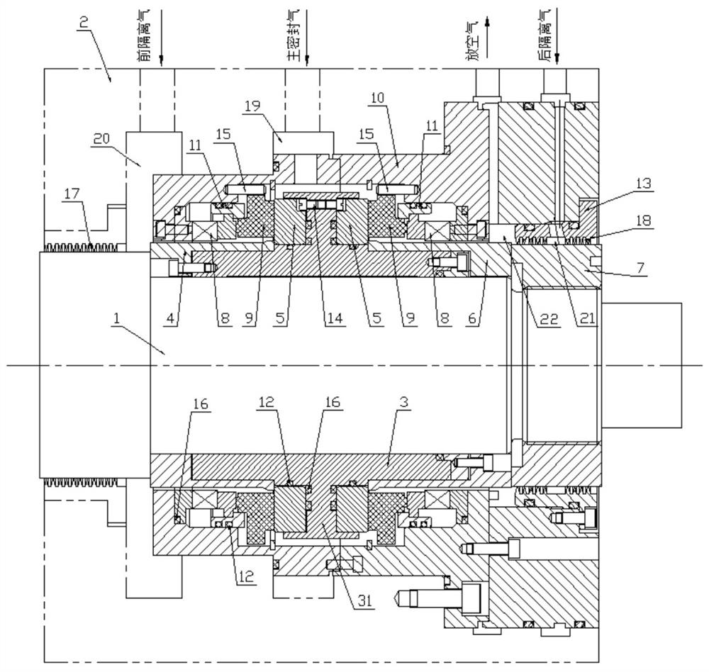
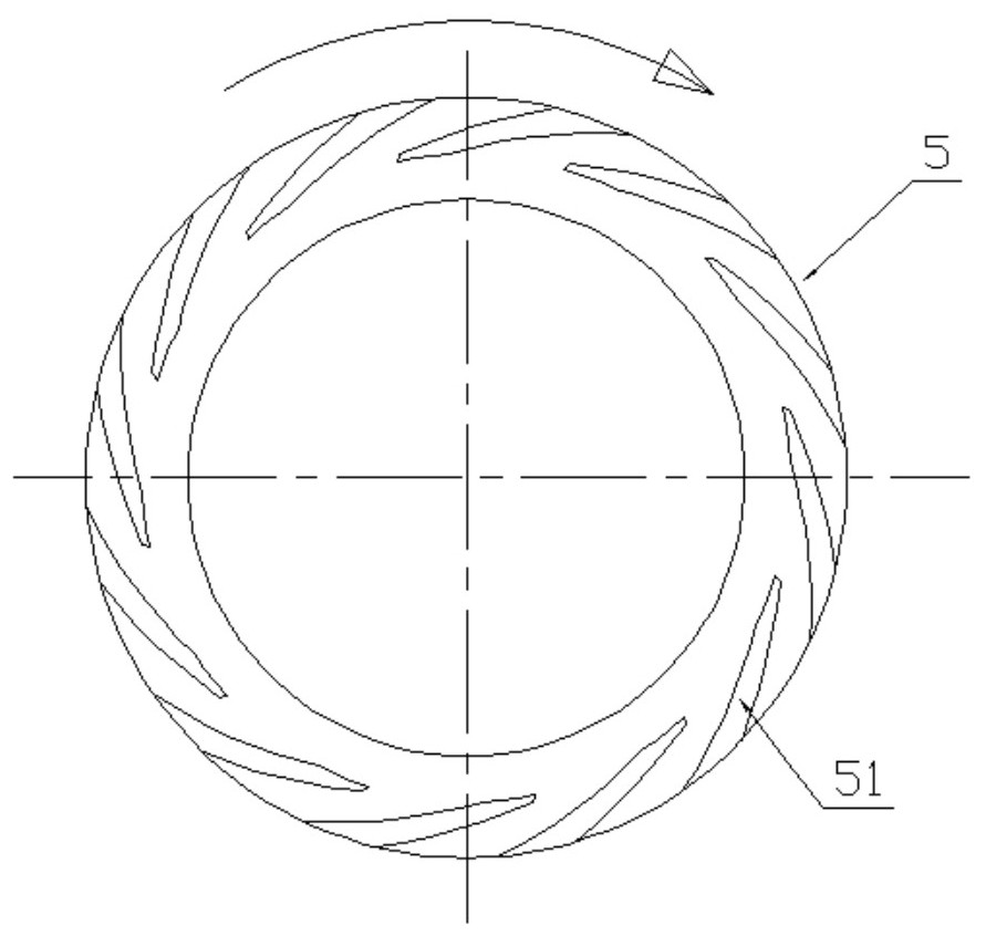
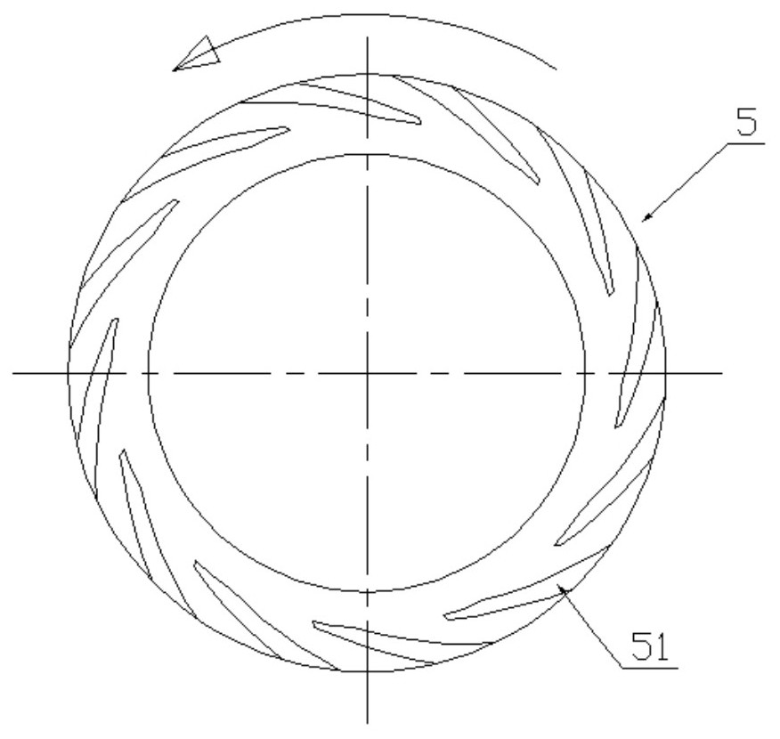
The invention discloses a double-end-face dry gas sealing device for an industrial steam turbine. The device comprises a rotary sealing assembly and a static sealing assembly; the rotary sealing assembly comprises a shaft sleeve fixed to a shaft neck, a shaft shoulder is arranged in the middle of the shaft sleeve, the two sides of the shaft shoulder are each provided with a movable ring, and pneumatic pressing grooves are formed in the movable rings; the static sealing assembly comprises a sealing sleeve fixed in a machine shell, and further comprises a pair of static rings and a pair of corrugated pipes, wherein the static rings and the corrugated pipes are arranged on the two sides of the shaft shoulder correspondingly; under the action of self elasticity, each corrugated pipe is pressedagainst the end surface of the static ring on the same side to form a contact sealing structure; and each static ring and the movable ring on the same side are oppositely arranged, and when the movable rings rotate along with a steam turbine shaft, a non-contact air film lubrication state is formed between the movable rings and the static rings. According to the device, the movable rings and thestatic rings have the self-adjusting capacity, so that stable gas film lubrication non-contact sealing is formed between the movable rings and the static rings, high-pressure steam is sealed in the steam turbine, zero-leakage sealing on the steam in the steam turbine is achieved, and the energy conversion efficiency of the steam turbine is greatly improved.

Description

technical field [0001] The invention relates to the technical field of mechanical seals, in particular to a double-face dry gas seal device for industrial steam turbines. Background technique [0002] The steam turbine is one of the main equipment of the steam power plant, and it is a rotary power machine that converts the energy of steam into mechanical work. The working principle of the steam turbine is that steam with a certain pressure and temperature enters the steam turbine, expands rapidly in the nozzle to obtain a high flow velocity, and then the high-speed flowing steam impels the turbine rotor blades to rotate and do work, thereby obtaining mechanical energy. A steam turbine is mainly composed of a rotating part, a fixed part and a control part. [0003] Industrial steam turbines are driven by steam, and are mainly used in chemical, petroleum, mining, metallurgy, papermaking, textile, sugar and other industrial enterprises. Industrial steam turbines drive various...

Claims


Application Information

Patent Timeline
IPC IPC(8): F01D11/04F01D11/06F01D25/00
CPCF01D11/04F01D11/06F01D25/005
Inventor 徐冉高立军刘闯
Owner 徐冉
Learn More