Condensing device with symmetric nozzles

A condensing device and symmetrically arranged technology, applied in the field of ship power, can solve the problems of difficult adjustment of liquid film quality, liquid leakage, shrinkage, etc.

Active Publication Date: 2020-10-23
WUHAN SECOND SHIP DESIGN & RES INST
View PDF9 Cites 4 Cited by
  • Summary
  • Abstract
  • Description
  • Claims
  • Application Information

AI Technical Summary

Problems solved by technology

Partitioning wall condensers, such as shell-and-tube heat exchangers and plate heat exchangers, are currently the main forms of condensers, and various problems have gradually been exposed during long-term operation: shell-and-tube heat exchangers have strong pressure bearing capacity, It has the advantages of not easy to scale, but its heat exchange capacity is limited, the volume and weight are large, and problems such as heat exchange tube bundle erosion and liquid leakage occur frequently
This method has the following problems: 1. A large volume of water chamber is required; 2. The quality of the liquid film is difficult to adjust, the thickness of the liquid film is too thick or it is difficult to maintain a stable liquid film; 3. The arrangement of the nozzles is limited, and the overall volume of the condenser is difficult to increase. Shrinkage; resulting in the heat transfer end difference between the hot and cold sides being greater than the design value, seriously affecting the efficiency and volume of the condenser
However, it still follows the design concept of the water chamber, and the quality of the liquid film needs to be further improved. Therefore, it is urgent to develop a new type of jet condenser research, innovate the control method of liquid film formation, reduce the volume of the condenser, and improve the efficiency of the condenser.

Method used


Image

  • Condensing device with symmetric nozzles
  • Condensing device with symmetric nozzles
  • Condensing device with symmetric nozzles

Examples


Embodiment Construction

[0023] In order to make the purpose, technical solutions and advantages of the embodiments of the present invention clearer, the technical solutions in the embodiments of the present invention will be clearly and completely described below in conjunction with the drawings in the embodiments of the present invention. Obviously, the described embodiments It is a part of embodiments of the present invention, but not all embodiments. Based on the embodiments of the present invention, all other embodiments obtained by persons of ordinary skill in the art without creative efforts fall within the protection scope of the present invention.

[0024] In the description of the present invention, it should be noted that unless otherwise specified and limited, the terms "installation", "connection" and "connection" should be understood in a broad sense, for example, it can be a fixed connection or a detachable connection. Connected, or integrally connected; it can be mechanically connected...


PUM


Abstract

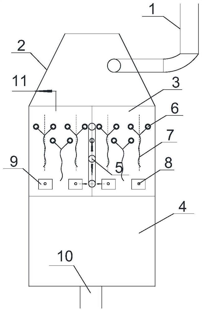
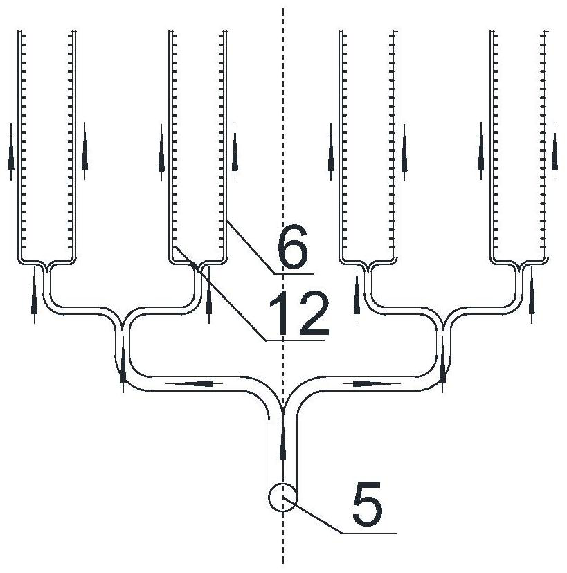
The invention relates to the field of ship power, and discloses a condensing device with symmetric nozzles. The condensing device comprises a condensing chamber; a cooling water inlet pipeline and a plurality of cooling branch pipes are mounted in the condensing chamber; each cooling branch pipe comprises two tail-stage branch pipes which are symmetrically arranged; and each tail-stage branch pipecommunicates with the cooling water inlet pipeline, and a plurality of groups of jet holes matched with each other are formed in each two symmetrically-arranged tail-stage branch pipes along the way.According to the condensing device with the symmetric nozzles provided by the invention, a traditional jet type condenser water chamber and baffle plate are saved, the cooling branch pipes are directly arranged in the condensing chamber, through the jet holes symmetrically formed in the tail-stage branch pipes, cooling water films are formed through impacting, so that for the condensing device with the symmetric nozzles, the water films can be directly utilized for cooling exhaust steam, and thus not only is the structure of the condensing device simplified, but also the compactness and condensing efficiency of the device are improved. Compared with the mode that jet flow impacts the baffle plate to form cooling water films, the mode provided by the invention is more direct, the quality of the water films is more convenient to regulate and control, and meanwhile, vibration noise is restrained.

Description

technical field [0001] The invention relates to the field of ship power, in particular to a symmetrical nozzle condensing device. Background technique [0002] The power system is the "heart" of marine platforms such as ships, which converts chemical energy or nuclear energy into propulsion power for marine platforms such as ships and provides electricity required for daily operation. Steam power cycle is one of the most common power systems. Condenser is The key equipment of the steam power system directly affects the efficiency and safety of the main unit and the turbogenerator unit. Partitioning wall condensers, such as shell-and-tube heat exchangers and plate heat exchangers, are the main forms of current condensers, and various problems have gradually been exposed during long-term operation: shell-and-tube heat exchangers have strong pressure bearing capacity, It has the advantages of not easy to scale, but its heat exchange capacity is limited, the volume and weight a...

Claims


Application Information

Patent Timeline
Patent Type & Authority Applications(China)
IPC IPC(8): F28B1/02F28B9/04
CPCF28B1/02F28B9/04
Inventor 肖颀柯汉兵柯志武田威李献领王苇柳勇李邦明李勇陈凯吴君魏志国王俊荣苟金澜庞杰黄崇海
Owner WUHAN SECOND SHIP DESIGN & RES INST
Why Eureka
Try Eureka