Static lower limb rehabilitation assistive device testing system
A technology of rehabilitation aids and testing systems, which is applied in general control systems, control/regulation systems, and testing of machine/structural components. It can solve the problems of inaccurate control and recording of parameters, high subjectivity, and low efficiency.
- Summary
- Abstract
- Description
- Claims
- Application Information
AI Technical Summary
Problems solved by technology
Method used
Image

Examples
Embodiment 1
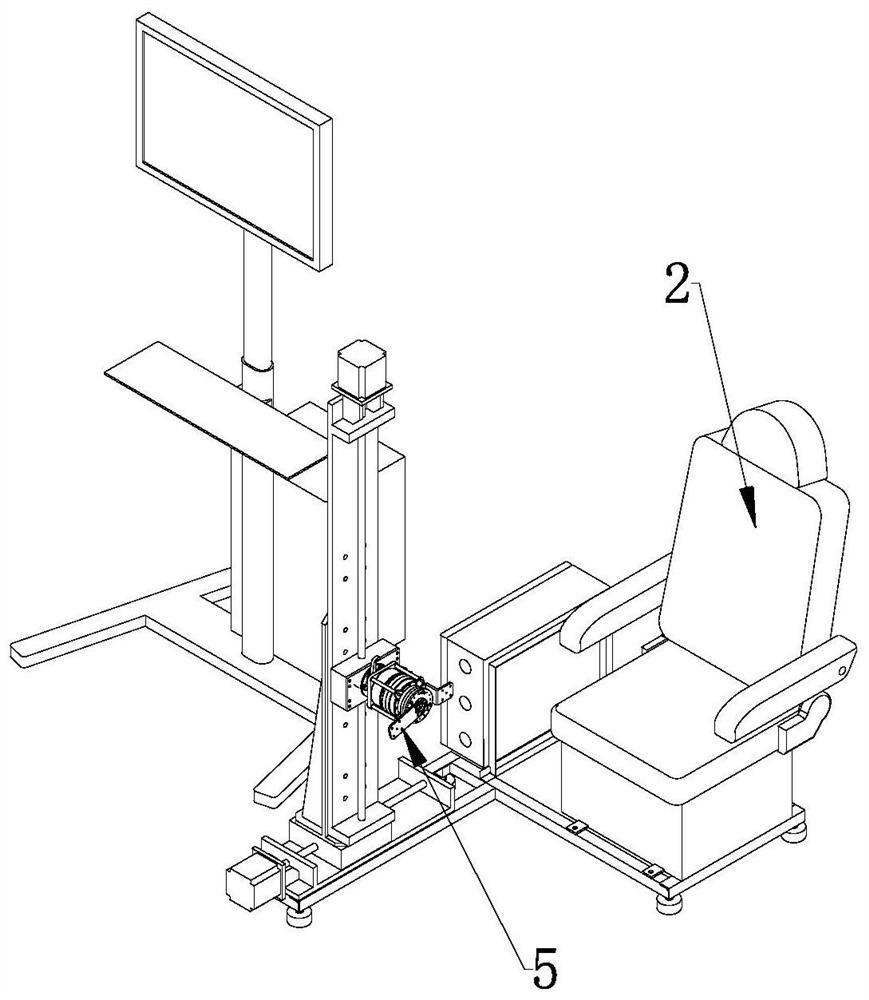
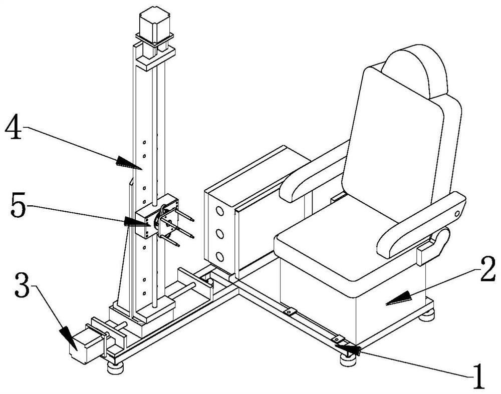
[0062] Such as Figure 1~2 As shown, it includes: a base 1, a moving device and a seat 2 fixed on the base 1, and the moving device includes: a horizontally arranged horizontal guide rail 3, a vertically arranged vertical guide rail 4 and a joint fixing structure 5, and the horizontal guide rail The bottom end of 3 is fixed on the base 1, and the vertical guide rail 4 is positioned at the side in front of the seat 2 (the front: the side where the patient sits on the leg of the seat), and the bottom end of the vertical guide rail 4 is connected to the horizontal guide rail 3. The slider is fixed, and the joint fixing structure 5 is fixed on the slider of the vertical guide rail 4 for installing rehabilitation aids. The rehabilitation aids are exoskeleton joint modules 8 or prosthetic limb modules 17 . By adjusting the sliding distance of the slide blocks on the horizontal guide rail 3 and the vertical guide rail 4, the position between the joint fixing structure 5 and the seat ...
Embodiment 2
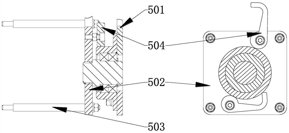
[0069] On the basis of Example 1, such as Figure 3-4 As shown, the joint fixing structure 5 includes: a bearing seat 501, a rotating bracket 502, a mounting rod 503 and a locking block 504, the bearing seat 501 is fixed to the slider of the vertical guide rail 4, the rotating bracket 502 is axially connected to the bearing seat 501 and can Rotate on the bearing seat 501, and a locking block 504 is installed on the rotating bracket 502, which is used to relatively fix the rotating bracket 502 and the bearing seat 501; Exoskeleton joint module 8 or prosthetic limb module 17.
[0070] Preferably, the rotating bracket 502 includes: a shaft and a fixed plate fixed to one end of the shaft, the rotating bracket 502 is connected to the bearing seat 501 through the other end of the shaft, and the mounting rod 503 is fixed on the fixing plate and is located away from the bearing seat 501 side.
[0071] Preferably, the number of mounting rods 503 is four, and the four mounting rods 50...
Embodiment 3
[0086] Such as Figure 8 As shown, on the basis of Embodiment 2, a relay 26 is provided on the circuit for controlling the motion of the joint motor 7 in the industrial computer 18 , and also includes: a single-chip microcomputer 6 for controlling the relay 26 . The relay is used to cut off the power supply in case of emergency in the experiment, which plays a role of safety protection.
[0087] Single-chip microcomputer 6 controls the motion of horizontal guide rail 3 and vertical guide rail 4. The position of the moving joint motor is realized by controlling the positions of the slide blocks on the horizontal guide rail 3 and the vertical guide rail 4 .
[0088] Preferably, when the rehabilitation aid is an exoskeleton joint module, a limit switch 27 is installed on the rehabilitation aid to limit the rotation limit of the joint motor 7 .
[0089] When the rehabilitation aid is an exoskeleton joint module, the travel switch 27 is arranged between the fixed end support 802 ...
PUM
 Abstract
Description
Claims
Application Information
 - R&D Engineer
- R&D Manager
- IP Professional
- Industry Leading Data Capabilities
- Powerful AI technology
- Patent DNA Extraction
Browse by: Latest US Patents, China's latest patents, Technical Efficacy Thesaurus, Application Domain, Technology Topic.
© 2024 PatSnap. All rights reserved.Legal|Privacy policy|Modern Slavery Act Transparency Statement|Sitemap