Photonic crystal microscopy and cell mechanics measurement methods

A technology of photonic crystals and microscopes, applied in microscopes, optics, measuring devices, etc., can solve the problems of sample interference, limited applications, and flux limitations, and achieve the effects of reducing influence, simplifying complexity, and improving throughput

Active Publication Date: 2020-12-25
江苏艾玮得生物科技有限公司
View PDF7 Cites 0 Cited by
  • Summary
  • Abstract
  • Description
  • Claims
  • Application Information

AI Technical Summary

Problems solved by technology

Therefore, high-resolution imaging is required to map high-resolution traction force, which greatly limits the application of this method.
High magnification objectives required for high resolution also limit throughput
High-dose phototoxicity will also cause greater interference to the sample to be tested
[0006] Although methods based on microcolumn arrays and methods based on fluorescence resonance energy transfer have been greatly developed, there are still limitations such as preparation difficulties and high requirements for measurement equipment.
In addition, the current method is limited to the mechanical measurement of macroscopic tissue or several microscopic cells, and cannot perform mechanical measurement with subcellular resolution within the millimeter field of view.

Method used


Image

  • Photonic crystal microscopy and cell mechanics measurement methods
  • Photonic crystal microscopy and cell mechanics measurement methods
  • Photonic crystal microscopy and cell mechanics measurement methods

Examples


Embodiment Construction

[0034] In order to enable those skilled in the art to better understand the technical solution of the present disclosure, the present disclosure will be described in further detail below in conjunction with the accompanying drawings and specific embodiments.

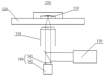
[0035] Such as figure 1As shown, a photonic crystal microscope 100 includes a photonic crystal substrate 110 , an object stage 120 , a detection light source 130 and an imaging component 140 .

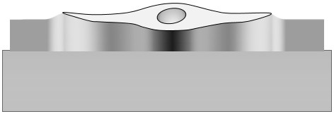
[0036] Exemplary, such as figure 1 As shown, the photonic crystal substrate 110 is set on the stage 120, and the photonic crystal substrate 110 is used for culturing the cells to be tested (not shown in the figure), and, when the cells to be tested are in the When growing on the photonic crystal substrate 110, the cell growth area causes the photonic crystal substrate 110 to deform, that is to say, in the photonic crystal microscope 100, the photonic crystal substrate 110 is also used for cultivating the cells to be tested. A s...


PUM

PropertyMeasurementUnit
thicknessaaaaaaaaaa
reflectanceaaaaaaaaaa
transmittivityaaaaaaaaaa

Abstract

Embodiments of the present disclosure provide a photonic crystal microscope and a method for measuring cell mechanics. The photonic crystal microscope includes a photonic crystal substrate, a stage, a detection light source and an imaging component. The photonic crystal substrate is above the stage, and the detection light source and imaging components are sequentially located on the side of the stage away from the photonic crystal substrate. The photonic crystal substrate is used for Cultivate the cells to be tested, and when the cells to be tested grow on the photonic crystal substrate, the photonic crystal substrate can be deformed; wherein, the detection light source is used to send detection light to the photonic crystal substrate; the photonic crystal substrate reflects the detection light to the imaging component The imaging component receives the reflected light from the photonic crystal substrate for imaging, so as to obtain the force information between the cells to be measured and the photonic crystal substrate by using the imaging graphics. On the premise of ensuring the accuracy of subcellular measurement, the throughput is greatly improved, the complexity of the algorithm is simplified, the time resolution is improved, and the cost of the device and the complexity of the experiment are reduced.

Description

technical field [0001] The disclosure belongs to the technical field of crystal microscopes, and in particular relates to a photonic crystal microscope and a method for measuring cell mechanics. Background technique [0002] Cell-generated forces are key regulators of cell adhesion, signaling, and function, and they are also important drivers of morphogenetic events in development. Over the past few decades, various methods have been developed to measure these forces. While there is great interest in understanding the contributions of these forces in biology, measuring them on a broad scale remains challenging. [0003] The simplest methods of characterizing the presence of cellular forces involve measuring deformations of cells, substrates, or tissues without attempting to relate these deformations to actual forces. For example, cells embedded in a collagen gel will compress the gel, mimicking the contraction that occurs during wound healing. The size of the cell force c...

Claims


Application Information

Patent Timeline
Patent Type & Authority Patents(China)
IPC IPC(8): G01N21/84G01N21/01G02B21/34G02B21/06G02B21/02G02B21/36G02B1/00
CPCG01N21/84G01N21/01G02B21/34G02B21/06G02B21/02G02B21/361G02B1/005G02B21/0076G02B26/007
Inventor 顾忠泽李奇维陈早早
Owner 江苏艾玮得生物科技有限公司
Why Eureka
Try Eureka